Model W1829 (Mfg. Since 9/11)
Checking/Adjusting Knife
Height
The knives MUST be level with the outfeed table when they are at top dead center (their highest point during rotation) or the workpiece cannot be safely fed across the jointer.
Tools Needed | Qty |
Hex Wrench 4mm | ................................................1 |
Hex Wrench 5mm | ................................................1 |
Checking Knife Height
1.DISCONNECT JOINTER FROM POWER SOURCE!
Make sure that your machine is unplugged during all service proce- dures! If this warning is ignored, seri- ous personal injury may occur.
SERVICE
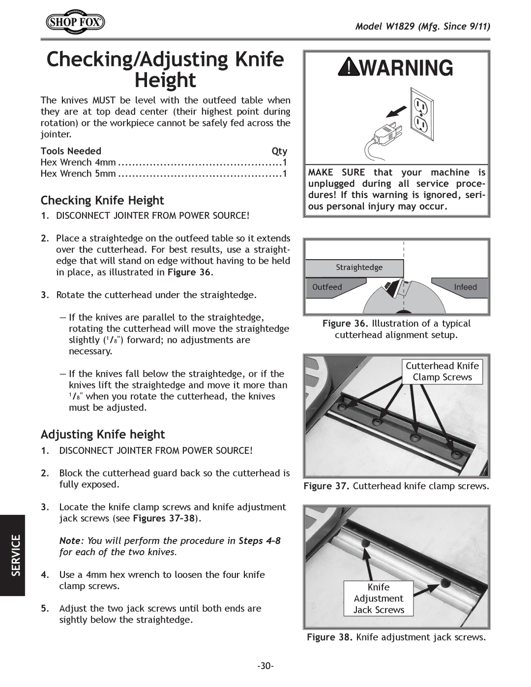
2.Place a straightedge on the outfeed table so it extends over the cutterhead. For best results, use a straight- edge that will stand on edge without having to be held in place, as illustrated in Figure 36.
3.Rotate the cutterhead under the straightedge.
—If the knives are parallel to the straightedge, rotating the cutterhead will move the straightedge slightly (1/8") forward; no adjustments are necessary.
—If the knives fall below the straightedge, or if the knives lift the straightedge and move it more than 1/8" when you rotate the cutterhead, the knives must be adjusted.
Adjusting Knife height
1.DISCONNECT JOINTER FROM POWER SOURCE!
2.Block the cutterhead guard back so the cutterhead is fully exposed.
3.Locate the knife clamp screws and knife adjustment jack screws (see Figures
Note: You will perform the procedure in Steps
4.Use a 4mm hex wrench to loosen the four knife clamp screws.
5.Adjust the two jack screws until both ends are sightly below the straightedge.
Straightedge |
|
Outfeed | Infeed |
Figure 36. Illustration of a typical
cutterhead alignment setup.
Cutterhead Knife |
Clamp Screws |