| Operation | |
| Command Summary | |
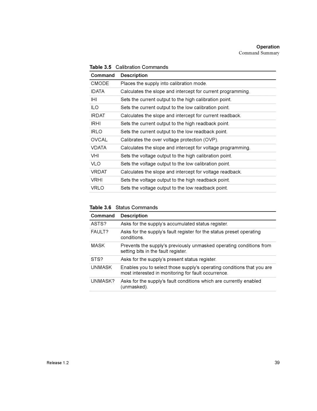
Table 3.5 | Calibration Commands |
|
Command | Description | |
|
|
|
CMODE | Places the supply into calibration mode. | |
|
|
|
IDATA | Calculates the slope and intercept for current programming. | |
|
|
|
IHI | Sets the current output to the high calibration point. | |
|
|
|
ILO | Sets the current output to the low calibration point. | |
|
|
|
IRDAT | Calculates the slope and intercept for current readback. | |
|
|
|
IRHI | Sets the current output to the high readback point. | |
|
|
|
IRLO | Sets the current output to the low readback point. | |
|
|
|
OVCAL | Calibrates the over voltage protection (OVP). | |
|
|
|
VDATA | Calculates the slope and intercept for voltage programming. | |
|
|
|
VHI | Sets the voltage output to the high calibration point. | |
|
|
|
VLO | Sets the voltage output to the low calibration point. | |
|
|
|
VRDAT | Calculates the slope and intercept for voltage readback. | |
|
|
|
VRHI | Sets the voltage output to the high readback point. | |
|
|
|
VRLO | Sets the voltage output to the low readback point. | |
|
|
|
Table 3.6 | Status Commands |
|
Command | Description | |
|
| |
ASTS? | Asks for the supply’s accumulated status register. |
|
|
|
|
FAULT? | Asks for the supply’s fault register for the status preset operating | |
| conditions. |
|
MASK | Prevents the supply's previously unmasked operating conditions from | |
| setting bits in the fault register. |
|
STS? | Asks for the supply’s present status register. | |
|
|
|
UNMASK | Enables you to select those supply's operating conditions that you are | |
| most interested in monitoring for fault occurrence. |
|
UNMASK? | Asks for the supply's fault conditions which are currently enabled | |
| (unmasked). | |
|
|
|
Release 1.2 | 39 |