Operating and start-up instructions
YLCC and YLCC-H control system
The YLCC and
-Local terminal. For accessing and controlling the system by means of the display, keys and LEDs. Allows selecting cool, heat and off functions. Also allows changing operat- ing parameters, as well as monitoring the system. Can be installed at a distance of 2 m. from the base plate. Is in- cluded inside the control panel and is to be connected to the base plate by means of an
Standard components
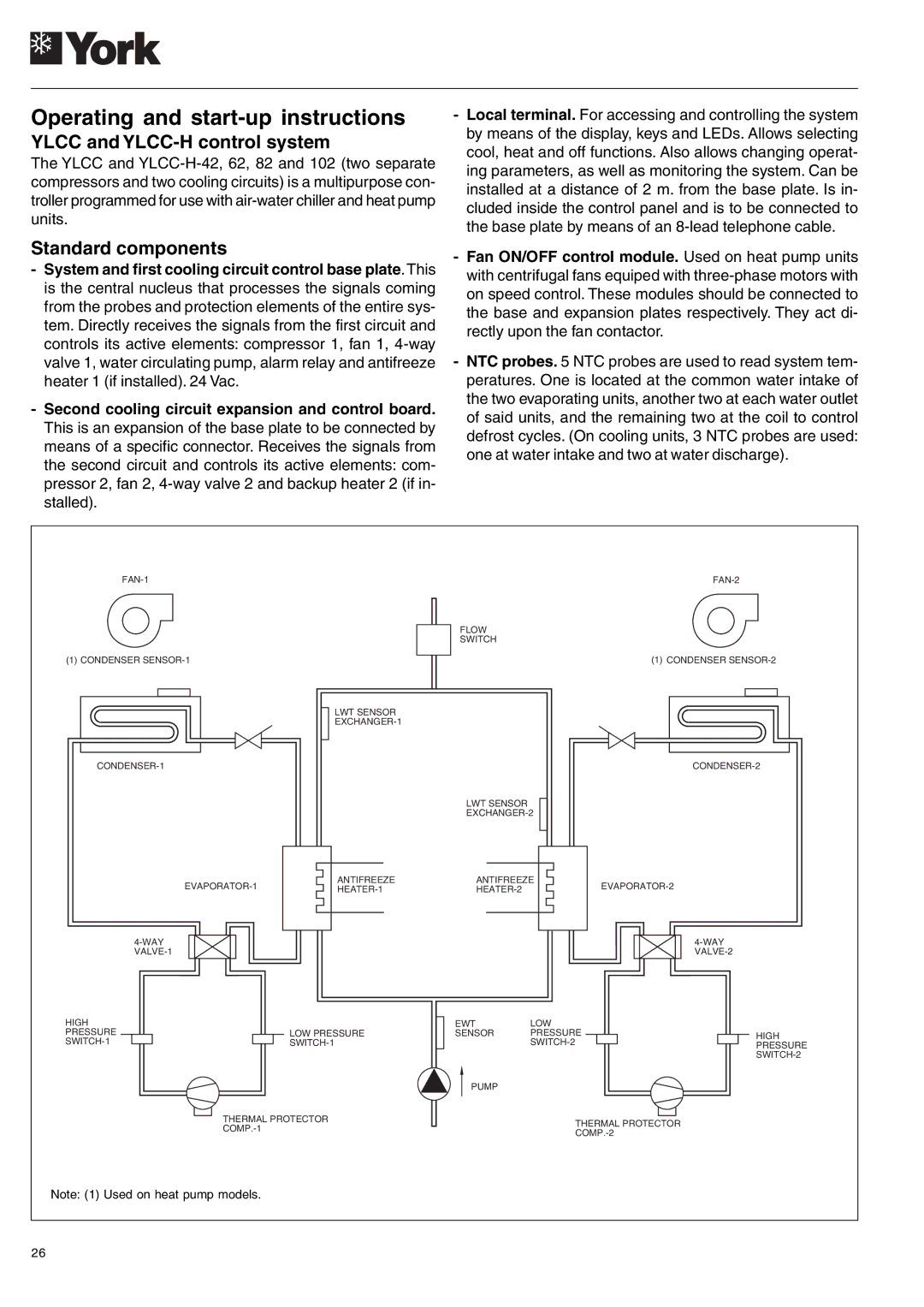
-System and first cooling circuit control base plate.This is the central nucleus that processes the signals coming from the probes and protection elements of the entire sys- tem. Directly receives the signals from the first circuit and controls its active elements: compressor 1, fan 1,
-Second cooling circuit expansion and control board. This is an expansion of the base plate to be connected by means of a specific connector. Receives the signals from the second circuit and controls its active elements: com- pressor 2, fan 2,
-Fan ON/OFF control module. Used on heat pump units with centrifugal fans equiped with
-NTC probes. 5 NTC probes are used to read system tem- peratures. One is located at the common water intake of the two evaporating units, another two at each water outlet of said units, and the remaining two at the coil to control defrost cycles. (On cooling units, 3 NTC probes are used: one at water intake and two at water discharge).
(1) CONDENSER
LWT SENSOR
ANTIFREEZE
FLOW
SWITCH
LWT SENSOR
ANTIFREEZE
(1) CONDENSER
HIGH PRESSURE
LOW PRESSURE
EWTLOW
SENSOR PRESSURE
PUMP
HIGH PRESSURE
THERMAL PROTECTOR
THERMAL PROTECTOR
Note: (1) Used on heat pump models.
26