51
(01) | (02) | (03) | (04) | (05) | (06) |
|
|
|
|
|
|
|
|
|
|
|
|
|
|
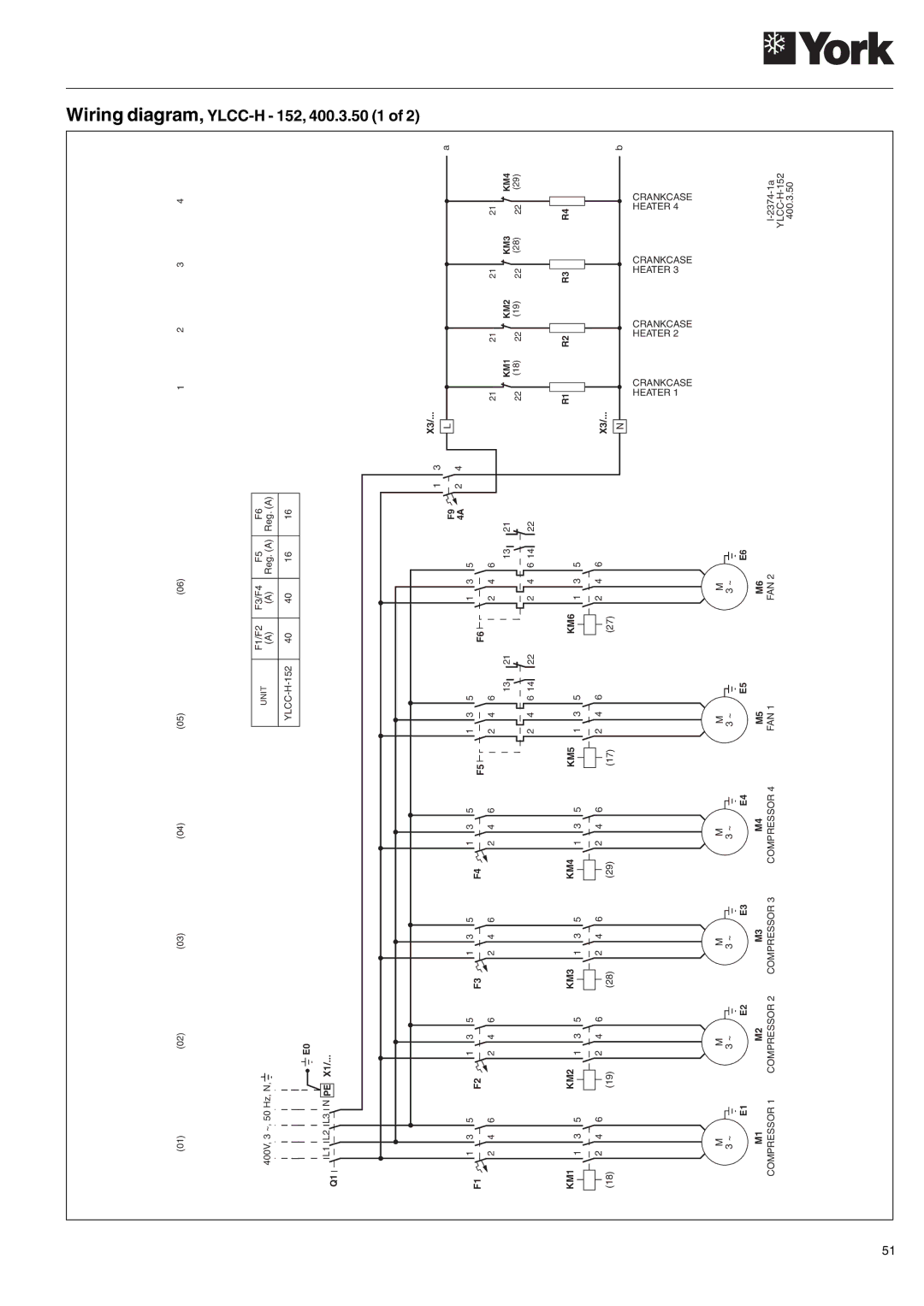
| UNIT | F1/F2 | F3/F4 | F5 | F6 |
| 400V, 3 ~, 50 Hz, N, |
|
|
|
|
|
|
| (A) | (A) | Reg. (A) | Reg. (A) | |||||||
|
|
|
| ||||||||||||||||
|
|
|
|
|
|
|
|
|
|
|
|
|
|
| 40 | 40 | 16 | 16 | |
|
|
|
|
|
|
|
|
|
|
|
|
|
| E0 |
|
|
|
|
|
|
|
|
|
|
|
|
|
|
|
|
|
|
|
|
|
|
|
| |
|
|
|
|
|
|
|
|
|
|
|
|
|
|
|
|
|
|
| |
|
|
|
|
|
|
|
|
|
|
|
|
|
|
|
|
|
|
| |
Q1 |
| L1 L2 L3 N PE X1/... |
|
|
|
|
| ||||||||||||
|
|
|
|
|
|
|
|
|
| ||||||||||
1 3
F9 ![]()
![]()
4A 2 4
1 | 3 | 5 | 1 | 3 | 5 | 1 | 3 | 5 | 1 | 3 | 5 |
|
|
|
|
|
| 1 | 3 | 5 |
|
|
|
|
|
|
| 1 | 3 | 5 |
| |||||||||||
F1 |
|
| F2 |
|
| F3 |
|
| F4 |
|
| F5 |
|
|
|
|
|
|
|
| F6 |
|
|
|
|
|
|
|
| |||||||||||||
2 | 4 | 6 | 2 | 4 | 6 | 2 | 4 | 6 | 2 | 4 | 6 |
|
| 2 | 4 | 6 |
|
|
| 2 | 4 | 6 |
| |||||||||||||||||||
|
|
|
|
|
|
|
|
|
|
|
|
|
| |||||||||||||||||||||||||||||
|
|
|
|
|
|
|
|
|
|
|
|
|
|
|
|
|
|
|
|
|
|
|
|
|
|
|
|
|
|
| 13 | 21 |
|
|
|
|
|
|
|
| 13 | 21 |
|
|
|
|
|
|
|
|
|
|
|
|
|
|
|
|
|
|
|
|
|
|
|
|
|
|
|
|
| 2 | 4 | 6 14 | 22 |
|
|
|
|
|
| 2 | 4 | 6 14 | 22 |
KM1 |
|
| KM2 |
|
| KM3 |
|
| KM4 |
|
|
| KM5 | 1 | 3 | 5 |
|
| KM6 | 1 | 3 | 5 |
| |||||||||||||||||||
| 1 | 3 | 5 |
|
| 1 | 3 | 5 |
|
| 1 | 3 | 5 |
|
| 1 | 3 | 5 |
|
|
|
|
|
|
|
|
|
|
|
|
|
| ||||||||||
|
|
|
|
|
|
|
|
|
|
|
|
|
|
|
|
|
| |||||||||||||||||||||||||
|
| 2 | 4 | 6 |
|
|
| 2 | 4 | 6 |
|
|
| 2 | 4 | 6 |
|
|
| 2 | 4 | 6 |
|
|
|
|
|
| 2 | 4 | 6 |
|
|
|
|
|
|
| 2 | 4 | 6 |
|
(18) |
|
|
| (19) |
|
|
| (28) |
|
|
| (29) |
|
|
| (17) |
|
|
|
|
| (27) |
|
|
|
|
| |||||||||||||||
M | M | M | M | M | M | |||||
3 ~ | 3 ~ | 3 ~ | 3 ~ | 3 ~ |
|
| 3 ~ |
|
| |
E5 | E6 | |||||||||
E1 | E2 | E3 | E4 |
|
| |||||
M1 | M2 | M3 | M4 | M5 | M6 | |||||
COMPRESSOR 1 | COMPRESSOR 2 | COMPRESSOR 3 | COMPRESSOR 4 | FAN 1 | FAN 2 | |||||
1 | 2 | 3 | 4 |
X3/... |
|
|
|
|
|
|
|
|
|
|
|
|
|
|
| ||
L |
|
|
|
|
|
|
|
|
|
|
|
|
|
|
|
| a |
|
|
|
|
|
|
|
|
|
|
|
|
|
|
|
| ||
21 |
|
| KM1 | 21 |
| KM2 | 21 |
|
| KM3 | 21 |
|
| KM4 | |||
|
|
|
| ||||||||||||||
|
|
|
|
|
|
|
|
|
|
|
|
| |||||
22 |
| (18) | 22 | (19) | 22 |
| (28) | 22 | (29) |
| |||||||
|
|
|
|
|
|
|
|
|
|
|
|
|
|
|
|
| |
| R1 |
|
|
| R2 |
|
|
| R3 |
|
|
| R4 |
|
|
|
|
|
|
|
|
|
|
|
|
|
|
|
|
|
|
|
|
| |
X3/... |
|
|
|
|
|
|
|
|
|
|
|
|
|
|
| ||
N |
|
|
|
|
|
|
|
|
|
|
|
|
|
|
|
| b |
|
|
|
|
|
|
|
|
|
|
|
|
|
|
|
| ||
| HEATER 1 | CRANKCASE | HEATER 2 | CRANKCASE | HEATER 3 | CRANKCASE | HEATER 4 | CRANKCASE | |||||||||