(a)Units with
Units with
(b)Units with
Units with
|
|
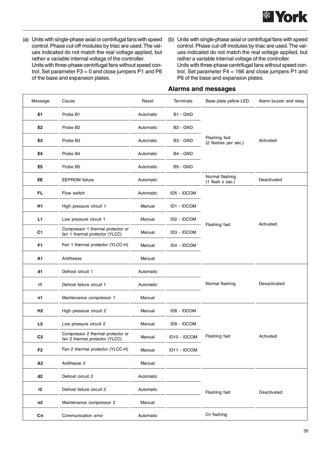
| Alarms and messages |
| ||
Message | Cause | Reset | Terminals | Base plate yellow LED | Alarm buzzer and relay | |
|
|
|
|
|
| |
E1 | Probe B1 | Automatic | B1 - GND |
|
| |
|
|
|
|
|
| |
E2 | Probe B2 | Automatic | B2 - GND |
|
| |
|
|
|
| Flashing fast | Activated | |
E3 | Probe B3 | Automatic | B3 - GND | |||
(2 flashes per sec.) | ||||||
|
|
|
|
| ||
|
|
|
|
|
| |
E4 | Probe B4 | Automatic | B4 - GND |
|
| |
|
|
|
|
|
| |
E5 | Probe B5 | Automatic | B5 - GND |
|
| |
|
|
|
|
|
| |
EE | EEPROM failure | Automatic |
| Normal flashing | Deactivated | |
| (1 flash x sec.) | |||||
|
|
|
|
| ||
|
|
|
|
|
| |
FL | Flow switch | Automatic | ID5 - IDCOM |
|
| |
|
|
|
|
|
| |
H1 | High pressure circuit 1 | Manual | ID1 - IDCOM |
|
| |
|
|
|
|
|
| |
L1 | Low pressure circuit 1 | Manual | ID2 - IDCOM |
| Activated | |
|
|
|
| Flashing fast | ||
C1 | Compressor 1 thermal protector or | Manual | ID3 - IDCOM | |||
|
| |||||
fan 1 thermal protector (YLCC) |
|
| ||||
|
|
|
|
| ||
|
|
|
|
|
| |
F1 | Fan 1 thermal protector | Manual | ID4 - IDCOM |
|
| |
|
|
|
|
|
| |
A1 | Antifreeze | Manual |
|
|
| |
|
|
|
|
|
| |
d1 | Defrost circuit 1 | Automatic |
|
|
| |
|
|
|
| Normal flashing | Desactivated | |
r1 | Defrost failure circuit 1 | Automatic |
| |||
|
|
|
|
|
| |
n1 | Maintenance compressor 1 | Manual |
|
|
| |
|
|
|
|
|
| |
H2 | High pressure circuit 2 | Manual | ID8 - IDCOM |
|
| |
|
|
|
|
|
| |
L2 | Low pressure circuit 2 | Manual | ID9 - IDCOM |
|
| |
|
|
|
|
|
| |
C2 | Compressor 2 thermal protector or | Manual | ID10 - IDCOM | Flashing fast | Activated | |
fan 2 thermal protector (YLCC) | ||||||
|
|
|
|
| ||
|
|
|
|
|
| |
F2 | Fan 2 thermal protector | Manual | ID11 - IDCOM |
|
| |
|
|
|
|
|
| |
A2 | Antifreeze 2 | Manual |
|
|
| |
|
|
|
|
|
| |
d2 | Defrost circuit 2 | Automatic |
|
|
| |
|
|
|
|
|
| |
r2 | Defrost failure circuit 2 | Automatic |
| Flashing fast | Deactivated | |
|
|
|
| |||
n2 | Maintenance compressor 2 | Manual |
|
|
| |
|
|
|
|
|
| |
Cn | Communication error | Automatic |
| Cn flashing |
| |
|
|
|
|
|
| |
35