Enterasys Networks 2G4082-25, 9034310-01 manual Card guides

Page 28

Installing Module into Matrix E7 or N7 Chassis

Caution: In step 4, do not force the locking levers to the point that they touch the face of the front panel. Forcing the locking levers to this point could damage the module and chassis.

Precaución: En el paso 4, tenga cuidado de no llevar las palancas de cierre a un punto en donde estén en contacto con el panel frontal. Si lo hace, podría dañar el módulo y/o el chasis.

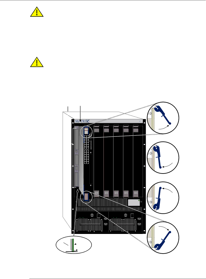
4.Refer to the Caution note above, then rotate the two levers into the closed position.

5.If the chassis in which the module is installed was powered down for the installation, turn the power supplies on. Check to see that the module CPU LED settles at solid green after a few minutes. If the LED does not turn solid green, refer to Chapter 4 for troubleshooting details.

Caution: When setting the locking levers to the closed position, do not try to force the locking levers to the point that they touch the face of the front panel. Forcing the locking levers to this point could damage the module and chassis.

Precaución: Al mover las palancas a la posición de cerrado, tenga cuidado de no llevarlas a un punto en donde estén en contacto con el panel frontal. Si lo hace, podría dañar el módulo o el chasis.

Figure 3-1 Installing Module into Matrix E7 or Matrix N7 Chassis (E7 shown)

ÆÁ

SERIES E7

1

2

3

4

5

6

7


Gb ENET


Ä


2G4082-25


Å


Å


DFE


LINE


LINE


ACON1

100-125V~12A


ACON1

100-125V~12A


200-240V~6A


200-240V~6A


50/60Hz


50/60Hz


0


0


POWER

FAN

POWER

FAN

LINE

100-125V~12A

200-240V~6A 50/60Hz

PS1

ÃÂ

À

LINE

Ä

100-125V~12A


200-240V~6A


50/60Hz


PS2

1

Card guides

5

Upper/lower locking tabs (in proper open position)

2

Slot number 1 (Left-most slot is 1.)

6

Upper/lower locking tab (in closed position)

3

Module card

7

Backplane connectors

4Metal back panel

3-4 Installation

Image 28
Contents Enterasys Matrix Page Page Regulatory Compliance Information Electromagnetic Compatibility EMC Supplement to Product Instructions Vcci Notice Enterasys NETWORKS, INC. Firmware License Agreement Vii Viii Contents Index Appendix a SpecificationsTables Who Should Use This Guide About This GuideImportant Notice How to Use This Guide Related DocumentsConventions Used in This Guide Getting HelpGetting Help Introduction Overview of DFE Series CapabilitiesDFE-Platinum Module 2G4082-25DFE Switch Configuration Using WebView Switch Configuration Using CLI CommandsNetwork Expansion Module NEM Option ConnectivitySecure Networks Policy Support Lanview Diagnostic LEDsStandards Compatibility Lanview Diagnostic LEDs Introduction Network Requirements Link Aggregation10BASE-T Network 100BASE-TX Network1000BASE-T Network 1000BASE-SX/LX/ELX NetworkInstallation Installing Module into Matrix E7 or N7 Chassis Installing Optional Network Expansion ModulesUnpacking the DFE-Platinum Module Installation PreparationCard guides Installing Module into Matrix N1, N3, or N5 Chassis Connecting to the Network Connecting UTP CablesConnecting a Twisted Pair Segment to the DFE-Platinum Module RX+ TX1+ RX1 TX2+ TX3+ RX3 RX2 TX4+ RX4 What Is Needed Connecting to COM Port for Local ManagementConnecting to an IBM PC or Compatible Device Connecting to a VT Series Terminal Connecting an IBM PC or CompatibleConnecting to a Modem Connecting a VT Series TerminalAdapter Wiring and Signal Assignments DB9Modem Port Adapter Wiring and Signal Diagram Completing the Installation of a New System First-Time Log-In Using a Console Port ConnectionLogging in with an Administratively-Configured User Account 11 Matrix DFE Startup Screen Example N7 ChassisTroubleshooting Using LanviewAbout the Management Mgmt LED Viewing the Receive and Transmit ActivityLED Alternating 67% on, 33% off Troubleshooting Checklist Series Configuration Guide for proper setupOverview of DFE-Platinum Module Shutdown Procedure Recommended Shutdown Procedure Specifications DFE-Platinum Module SpecificationsCOM Port Pinout Assignments Regulatory ComplianceSetting the Mode Switches Mode Switch Bank Settings Optional InstallationsRequired Tools Memory Locations and Replacement Procedures Figure B-1 Mode Switch Location on 2G4082-25Location of Memory Modules Flash Dimm Replacement ProcedureRemoving the Dimm from 2G4082-25 Figure B-3 NEM Removal and Dimm Connector Location Installing the Dimm DimmInstalling the Dram Simm Dram Simm Replacement ProcedureRemoving the Dram Simm Figure B-7 Installing the Dram Simm Page Index NumericsIndex-2