Transcend Information TS32M~1GCF80 dimensions Contiguous I/O Mapped Addressing

Page 37

TS32M~1GCF80

80X CompactFlash Card


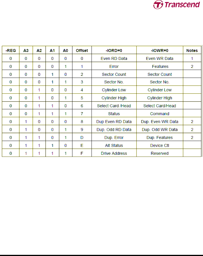
5.2 Contiguous I/O Mapped Addressing

When the system decodes a contiguous block of I/O registers to select the CompactFlash Storage Card, the registers are accessed in the block of I/O space decoded by the system as follows:

Table: Contiguous I/O Decoding

Notes:

1)Register 0 is accessed with -CE1 low and -CE2 low (and A0 = Don’t Care) as a word register on the combined Odd Data Bus and Even Data Bus (D15-D0). This register may also be accessed by a pair of byte accesses to the offset 0 with -CE1 low and -CE2 high. Note that the address space of this word register overlaps the address space of the Error and Feature byte-wide registers that lie at offset

1.When accessed twice as byte register with -CE1 low, the first byte to be accessed is the even byte of the word and the second byte accessed is the odd byte of the equivalent word access.

A byte access to register 0 with -CE1 high and -CE2 low accesses the error (read) or feature (write) register.

2) Registers at offset 8, 9 and D are non-overlapping duplicates of the registers at offset 0 and 1.

Register 8 is equivalent to register 0, while register 9 accesses the odd byte. Therefore, if the registers are byte accessed in the order 9 then 8 the data shall be transferred odd byte then even byte.

Repeated byte accesses to register 8 or 0 shall access consecutive (even than odd) bytes from the data buffer. Repeated word accesses to register 8, 9 or 0 shall access consecutive words from the data buffer. Repeated byte accesses to register 9 are not supported. However, repeated alternating byte accesses to registers 8 then 9 shall access consecutive (even then odd) bytes from the data buffer. Byte accesses to register 9 access only the odd byte of the data.

3) Address lines that are not indicated are ignored by the CompactFlash Storage Card for accessing all the registers in this table.

Transcend Information Inc.

37

V1.1

Image 37
Contents Dimensions Placement FeatureDescription 80X CompactFlash CardCHS and Capacity Ordering InformationCompactflash Card Specification Block Diagram Electrical Interface Pin Assignment and Pin Type PC Card Memory Mode PC Card I/O Mode True IDE Mode4V1.1 Signal Name Dir Pin Description Signal DescriptionCsel V1.1 Iord REG True IDE Mode As Iordy Input Leakage Current Electrical SpecificationParameter Symbol Min Max Unit Remark Input Characteristics CompactFlash interface I/O atMin Max Unit ParameterOutput Drive Type Output Drive Characteristics Signal Card Host Signal Interface150 μ a high state per socket TS32M~1GCF8080X CompactFlash CardAttribute Memory Read Timing Figure Attribute Memory Read Timing DiagramConfiguration Register Attribute Memory Write Timing Cycle Time Mode 250 ns 120 ns 100 ns 80 ns Common Memory Read Timing SpecificationMin Max Symbol Min Symbol Common Memory Write Timing Specification80X CompactFlash Card I/O Input Read Timing SpecificationCycle Time Mode 255 ns 120 ns 100 ns 80 ns 10 I/O Output Write Timing SpecificationMode True IDE PIO Mode Read/Write Timing SpecificationV1.1 True IDE Multiword DMA Mode Read/Write Timing Specification Multiple Function CompactFlash Storage Cards Card ConfigurationCE2 CE1 A10 A8-A4Attribute Memory Function Function ModeCE2 CE1 A10 D15-D8 D7-D0 Configuration Option RegisterBase + 00h in Attribute Memory Table CompactFlash Storage Card ConfigurationsTable Pin Replacement Changed Bit/Mask Bit Values Pin Replacement Register Base + 04h in Attribute MemoryI/O Transfer Function Socket and Copy Register Base + 06h in Attribute MemoryTable Pcmcia Mode I/O Function True IDE Mode I/O Transfer FunctionCommon Memory Transfer Function Function Code V1.1 CF-ATA Drive Register Set Definition and Protocol Table I/O ConfigurationsTable Primary and Secondary I/O Decoding I/O Primary and Secondary Address ConfigurationsTable Contiguous I/O Decoding Contiguous I/O Mapped AddressingMemory Mapped Addressing CF-ATA Registers True IDE Mode AddressingData Register Address 1F0h170hOffset 0,8,9 Table Data Register Access Error Register Address 1F1h171h Offset 1, 0Dh Read OnlySector Count Register Address 1F2h172h Offset Feature Register Address 1F1h171h Offset 1, 0Dh Write OnlySector Number LBA 7-0 Register Address 1F3h173h Offset Cylinder Low LBA 15-8 Register Address 1F4h174h OffsetFigure Status & Alternate Status Register Device Control Register Address 3F6h376h Offset EhFigure Device Control Register Card Drive Address Register Address 3F7h377h Offset FhCF-ATA Command Description LBA CF-ATA Command SetDefinitions Execute Drive Diagnostic 90h Check Power Mode 98h or E5hBit Command Cyl High Cyl Low Sec Num Sec Cnt FeatureFormat Track 50h Erase Sectors C0hDrive Head LBA Cyl High Sec Num LBA Sec CntIdentify Device Ech Word Default Total Data Field Type InformationBytes Total Data Field Type Information Word 1 Default Number of Cylinders Word 0 General ConfigurationWord 3 Default Number of Heads Word 6 Default Number of Sectors per TrackPIO Data Transfer Cycle Timing Mode Word 49 Capabilities Bit 13 Standby TimerMultiple Sector Setting Total Sectors Addressable in LBA ModeWord 64 Advanced PIO transfer modes supported Multiword DMA transferWord 65 Minimum Multiword DMA transfer cycle time Recommended Multiword DMA transfer cycle timeWords 85-87 Features/command sets enabled Words 82-84 Features/command sets supportedWord 68 Minimum PIO transfer cycle time with Iordy Word 89 Time required for Security erase unit completion Word 91 Advanced power management level valueWord 128 Security Status Bit 8 Security Level Value Maximum PIO mode timing selected Word 160 Power Requirement DescriptionAdditional Requirements for CF Advanced Timing Modes Value Current PIO timing mode selected Value Maximum Multiword DMA timing mode supportedValue Current Multiword DMA timing mode selected Value Maximum Pcmcia IO timing mode SupportedIdle 97h or E3h Drive Cyl High Cyl Low Sec Num Sec Cnt FeatureIdle Immediate 95h or E1h Initialize Drive Parameters 91hRead DMA C8h Read Buffer E4hRead Multiple C4h Read Verify Sectors 40h or 41h Read Sectors 20h or 21hRequest Sense 03h Recalibrate 1XhSeek 7Xh Table Extended Error CodesTable Feature Supported Set Features EFhSet Multiple Mode C6h Standby 96h or E2h Set Sleep Mode- 99h or E6hTranslate Sector 87h Standby Immediate 94h or E0hTableTranslate Sector Information Write Buffer E8h Wear Level F5hWrite DMA CAh Write Multiple Command C5h Write Sectors 30h or 31h Write Multiple without Erase CDhWrite Verify 3Ch Write Sectors without Erase 38hBBK UNC Idnf Abrt Amnf Drdy DWF DSC Corr ERR 80X CompactFlash Card Error PostingCIS Description Address Data Description of Contents CIS functionAddress Data 5 4 Description of Contents CIS function Cistplconfig V1.1 MS IR IO RO a Address Data 5 4 3 2 1 Description of Contents CIS function Irqn LS AS NR RO a T