Panasonic WJ-RT208 manual When using WJ-SX150, When using WJ-MP204

Page 19

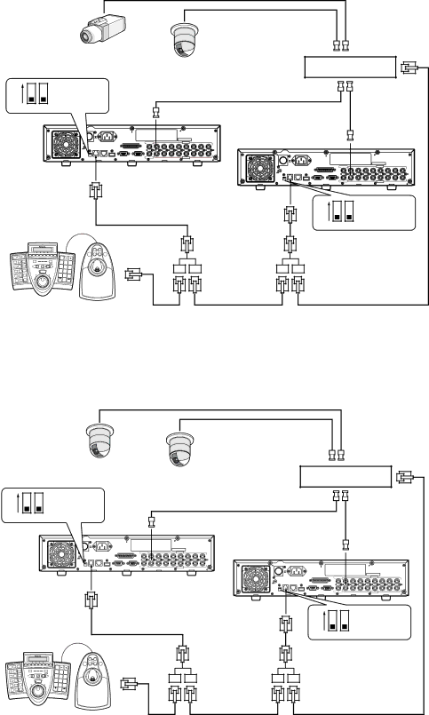
When controlling cameras with coaxial and PS·Data communication systems

When using WJ-SX150

System camera

Combination


camera

Matrix switcher Termination: ON Unit address: 1 - 4

ON

Mode switch


BNC cable (option)


1

2


BNC cable


(option)


ON


Second unit


OFF


Unit address (system): 6


POWER

AC IN


AUDIO OUT

2

3

4

AUDIO IN

6

7

8


1

5


SIGNAL GND


TERMINAL/CONTROL


1

2

3

4

5

6

7

8


MODE DATA 10/100BASE-T

COPY1

SERIAL

MONITOR(VGA) VIDEO OUT


VIDEO IN


ON


OFF


POWER

AC IN


AUDIO OUT

2

3

4

AUDIO IN

6

7

8

First unit (this unit)


1

5


SIGNAL GND


TERMINAL/CONTROL


Unit address (system): 5


SERIAL MONITOR(VGA)

1

2

3

4

5

6

7

8


MODE DATA 10/100BASE-T

COPY1

VIDEO OUT


VIDEO IN


Controller


ON


RS485 cable


Mode switch

Termination: ON


1

2


RS485 cable


Unit address: 1


A

B


1

2

3


4

5

6


7

8

9


0


RS485 cable


RS485 cable


RS485 cable

(provided with the controller)

When using WJ-MP204

Combination cameras

Data multiplex unit Termination: ON Unit address: 3

ON

Mode switch


BNC cable (option)


1

2


BNC cable


(option)


ON


Second unit


POWER

AC IN


AUDIO OUT 1

2

3

4

5

6

7

8

Unit address (system): 2


OFF


AUDIO IN


SIGNAL GND


TERMINAL/CONTROL


1

2

3

4

5

6

7

8


MODE DATA 10/100BASE-T

COPY1

SERIAL MONITOR(VGA) VIDEO OUT


VIDEO IN


ON


OFF


POWER

AC IN


AUDIO OUT

2

3

4

AUDIO IN

6

7

8

First unit (this unit)


1

5


SIGNAL GND


TERMINAL/CONTROL


Unit address (system): 1


SERIAL MONITOR(VGA)

1

2

3

4

5

6

7

8


MODE DATA 10/100BASE-T

COPY1

VIDEO OUT


VIDEO IN


Controller


ON


RS485 cable


Mode switch

Termination: ON


1

2


RS485 cable


Unit address: 1


A

B


1

2

3


4

5

6


7

8

9


0


RS485 cable


RS485 cable


RS485 cable


(provided with the controller)


19

Image 19
Contents Operating Instructions Lightning flash with arrowhead symbol Important Safety Instructions Limitation of Liability Disclaimer of WarrantyTrademarks and Registered Trademarks PrecautionsAbout These Operating Instructions Contents Preface FeaturesFront View Major Operating Controls & Their Functions← Left button 6Cancel Button ESC@6Copy Connector Copy ↓ Down buttonRear View About mounting InstallationInstalling the Hard Disk Places to avoidMaster HDD of IDE port HDD connected to IDE port Slave HDD Page Basic Connection System Composition and ConnectionsBasic System Example for Basic System ConnectionsWJ-RT208 Connection with RS485 CameraDirect PC Connection Connection with External HDD For Data BackupNetwork System Example for Network System ConnectionConnections with a Broadband WAN Network Connections with any Existing Network SystemUser type When connecting multiple units with a controller When connecting a single unit with a controllerConnection with PS·Data systems When using WJ-MP204 When using WJ-SX150RS485 Connection Pin No Signal Operation RemarksDIP Switch Setting User Registration Setup ProceduresTurning the Power On PreparationBasic Operation of the Menu Main menu Submenu Example Menu typeTime & Date YYYY-MM-DD Hhmmss Turning the Power Off2005-01-28 Cancel Modification of the System TimePlayback of Recorded Image OperationScreen Operation Manual RecordingAction at an event Operations for EventsPlayback the record Event typePTZ Setup PTZ Select Preset Information Cancellation of alarmCamera Control Panasonic RS485 SetupPanning/Tilting Auto function Auto Pan, etcFocus To register preset position of camerasTo display the camera setting menu ZoomControl this Unit with a PC Computer configurationOutlined functions Setting Item Description SetupSystem Management System MAN Operation for Various SettingsNtsc Time & date Time & Date Reboot system Reboot SystemPicture adjustment Picture Adjust Disk information Disk InformationTerminal recording Terminal REC Recording & event setup REC & EventTimer recording Timer REC Record search SearchVideo motion detector recording VMD REC Record length Record Length VMD Area Setup Area SetupTime Per File 015 Min Cancel Setup enabled range 005PTZ selection PTZ Select PTZ setup PTZ SetupCamera setup Camera Setup Preset position information Preset INFORMA- TionNetwork setup Network Setup Communication setup CommunicaTCP Data port setup Data Port Setup RS485 setup RS485 SetupSystem log System LOG Report ReportReport System LOG Event LOG Oldest Data Information Oldest data information Oldest Data Infor User level setup User Level SetupUser information User Information Event log Event LOGOnline user information Online User INFORMA- Tion Password PasswordDo you really want to lock keyboard ? Cancel Data management Data MANAGE- Ment2004-10-22 2004-10-27 Backup by External HDDSearch and Playback Channel No Start End Event Only2004-10-10 Data Management Factory Default BackupDisk Format All data will be deleted Will you continue ? CancelDisk Management HDD formattingRecovery of hard disk index Returning the Configuration to the Default SettingsOrdinary screen 9-split screen System Screen ExplanationsScreen in a certain channel System Management System Management Setup Menu Parameters and Initial Setup ValuesTerminal Recording Terminal REC Recording & Event Setup REC & EventTimer Recording Timer REC Recording Search SearchPTZ Setup PTZ Setup RS485 Setup RS485 Setup Camera Setup Camera SetupCommunication Setup Communication Setup Network Setup Network SetupOldest Data Information Oldest Data Information Report ReportSystem Log System LOG Event Log Event LOGData Management Data Management User Information User InformationOperation using the WV-CU650 Operation using the system controllerAvailable only during playback Problem Check item/remedy TroubleshootingInput/Output SpecificationsBasic Specifications GeneralTable of Recording Length Standard AccessoriesPage Ns0306-1046 3TR004320BAA