Model SB1023 | O P E R A T I O N | For Machines Mfg. Since 8/09 |
Controls
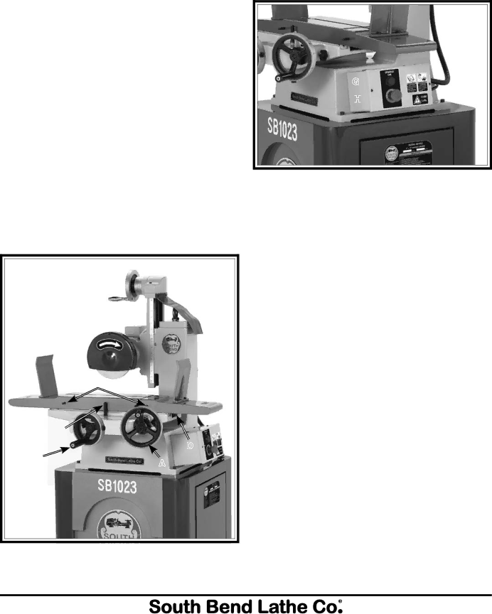
Refer to Figures
A.Longitudinal Travel Handwheel: Moves the table back and forth along the longitudinal axis
B.Center Table Stop: Provides a barrier for the table stops to limit table movement.
C.Table Stop: Adjusts along the length of the table to limit longitudinal travel.
D.Cross Axis Lock Knob: Locks the cross table movement
E.Elevation Handwheel: Controls vertical movement of the grinding wheel assembly.
F.Cross Travel Handwheel: Moves the table forward and backward along the cross axis
G.Spindle On Button: Supplies power to the grinding wheel motor.
H.Emergency Stop (Off) Button: Cuts power to the grinding wheel motor.
G ![]()
H![]()
![]()
![]()
Figure 11. Control panel.
E![]()
![]()
![]()
![]()
C
| B | |
F | D | |
A | ||
|