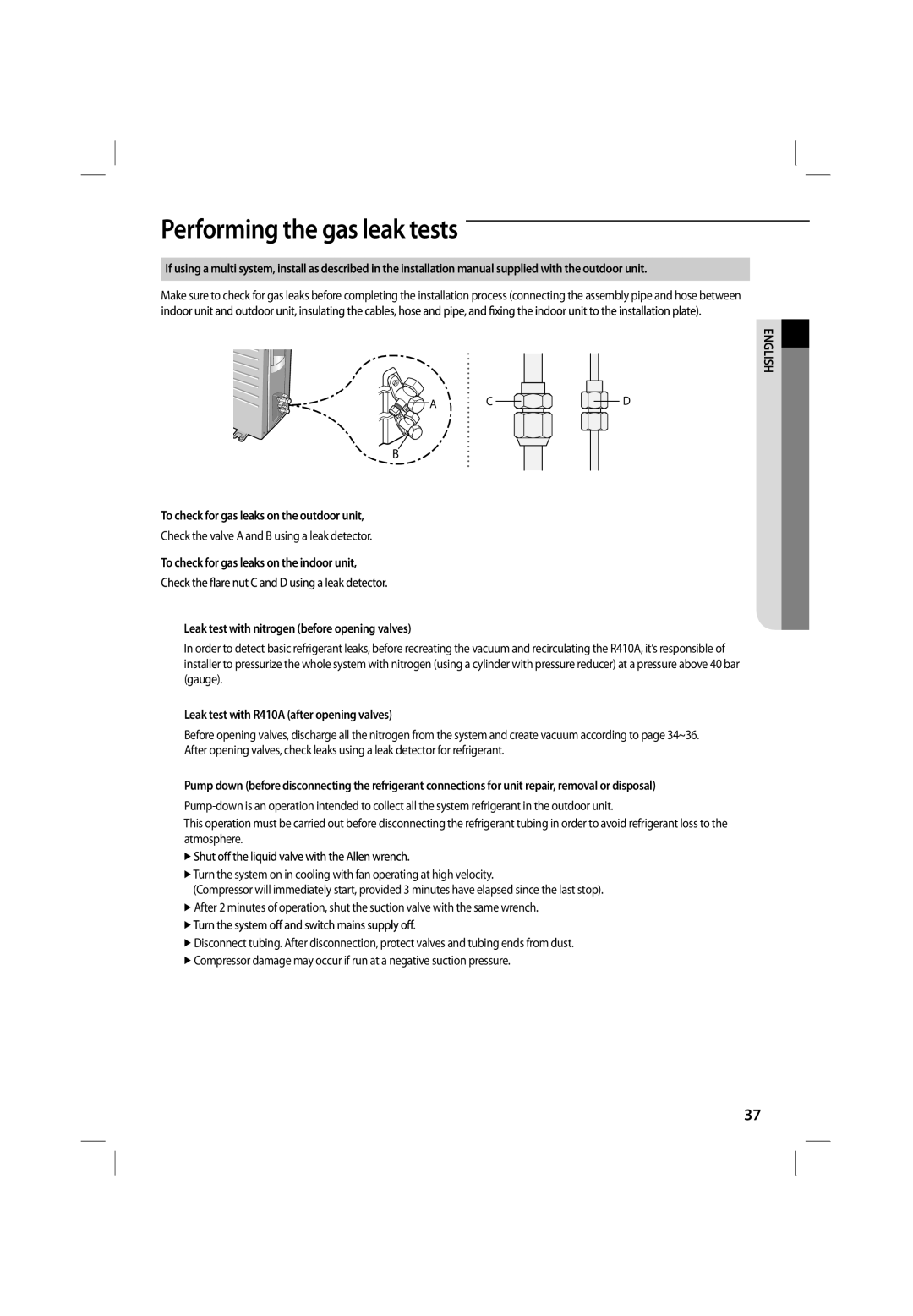
Samsung ASV18PSPNXEA manual Smooth the cut edges, Then pull it out through the appropriate hole

Page 30

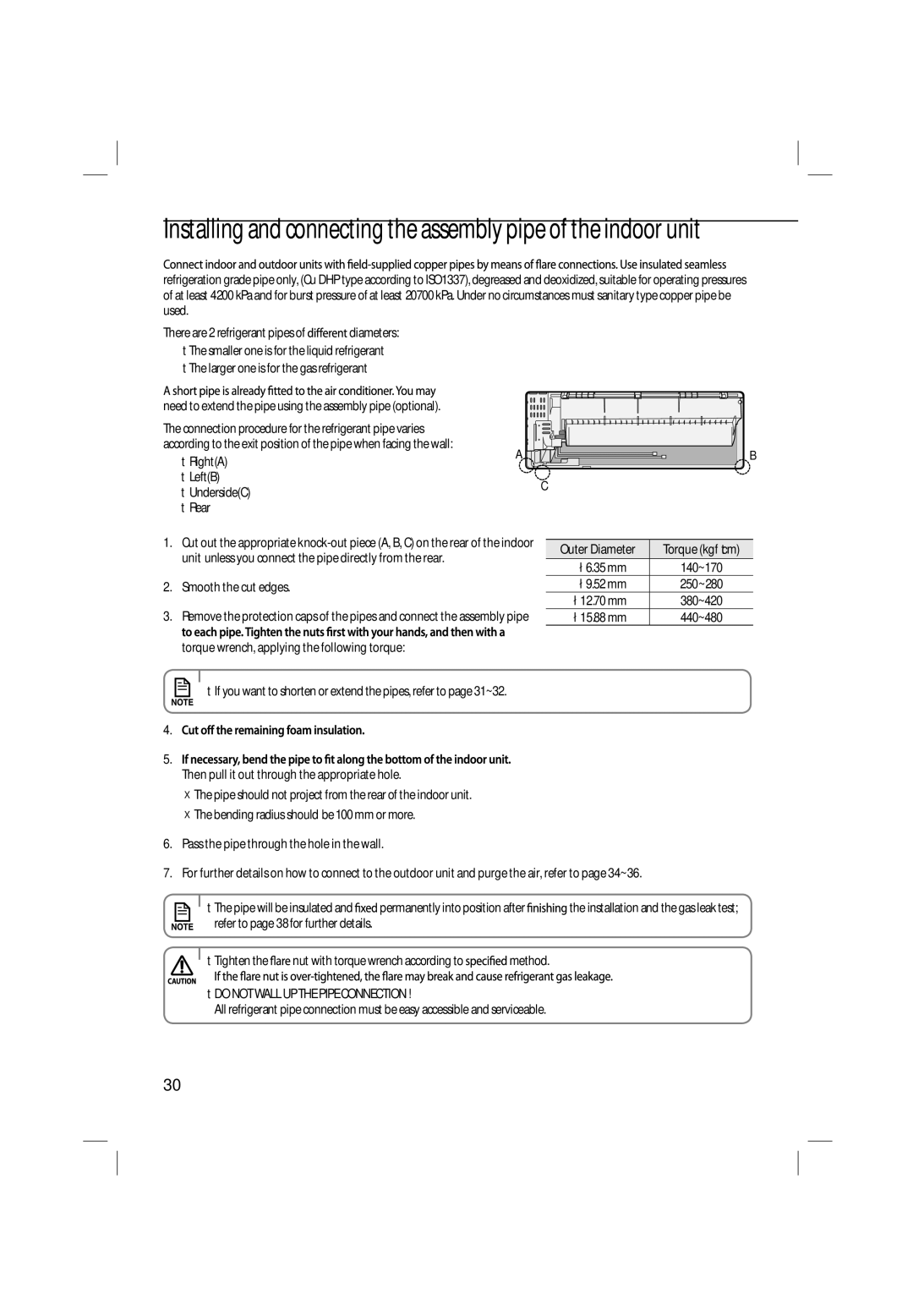
Installing and connecting the assembly pipe of the indoor unit

refrigeration grade pipe only, (Cu DHP type according to ISO1337), degreased and deoxidized, suitable for operating pressures of at least 4200 kPa and for burst pressure of at least 20700 kPa. Under no circumstances must sanitary type copper pipe be used.

There are 2 refrigerant pipes of diameters:

The smaller one is for the liquid refrigerant

The larger one is for the gas refrigerant

need to extend the pipe using the assembly pipe (optional).

The connection procedure for the refrigerant pipe varies


according to the exit position of the pipe when facing the wall:

A

B

Right(A)


Left(B)


C

Underside(C)


Rear

1.Cut out the appropriate knock-out piece (A, B, C) on the rear of the indoor unit unless you connect the pipe directly from the rear.

2.Smooth the cut edges.

3.Remove the protection caps of the pipes and connect the assembly pipe torque wrench, applying the following torque:

Outer Diameter

Torque (kgf•cm)


ø6.35 mm

140~170

ø9.52 mm

250~280

ø12.70 mm

380~420

ø15.88 mm

440~480

• If you want to shorten or extend the pipes, refer to page 31~32.

4.

5.

Then pull it out through the appropriate hole.

The pipe should not project from the rear of the indoor unit.

The bending radius should be 100 mm or more.

6.Pass the pipe through the hole in the wall.

7.For further details on how to connect to the outdoor unit and purge the air, refer to page 34~36.

• The pipe will be insulated and

permanently into position after

the installation and the gas leak test;

refer to page 38 for further details.


• Tighten thenut with torque wrench according tomethod.

DO NOT WALL UP THE PIPE CONNECTION !

All refrigerant pipe connection must be easy accessible and serviceable.

30
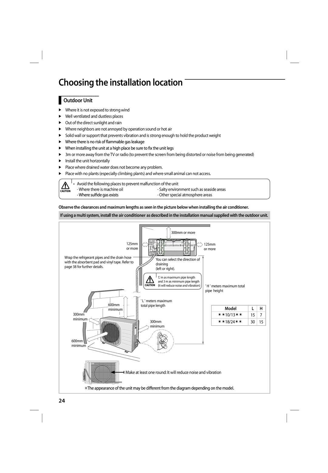
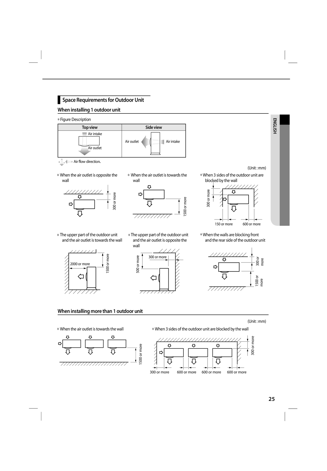
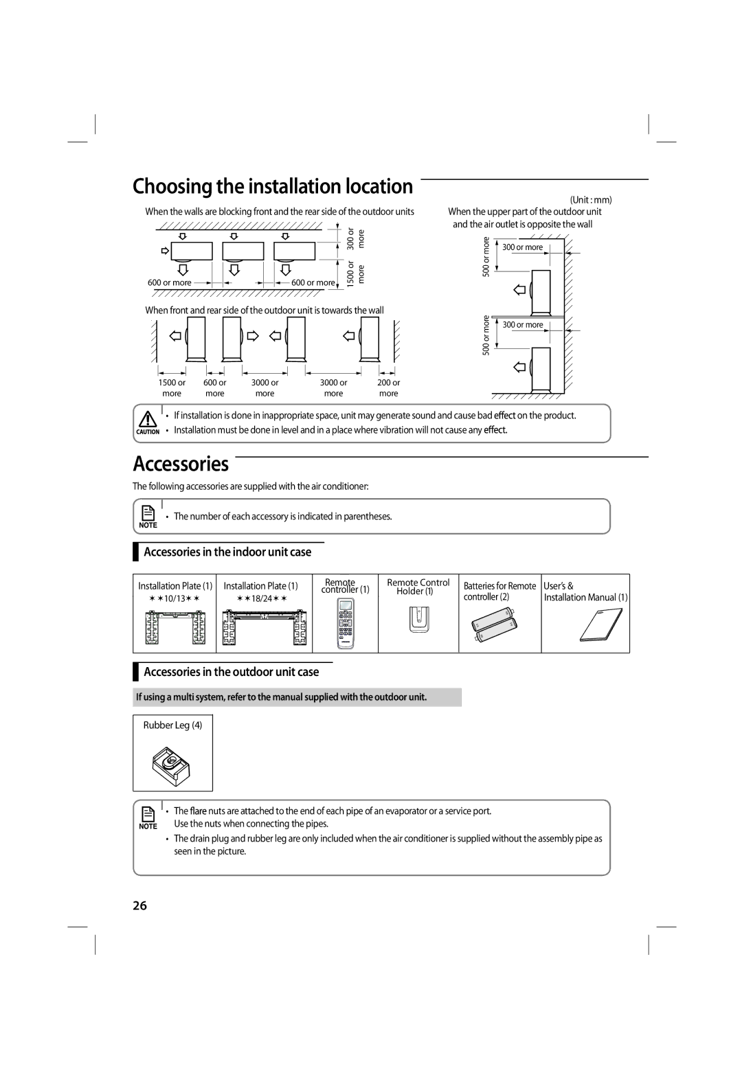
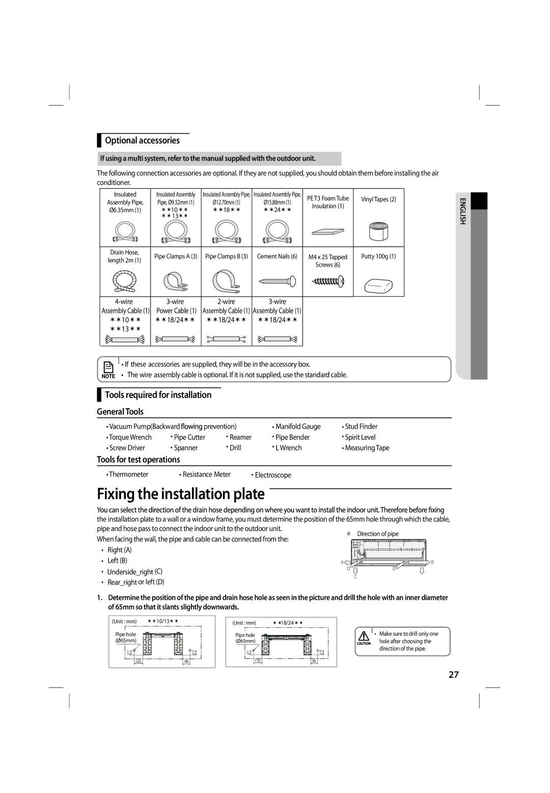
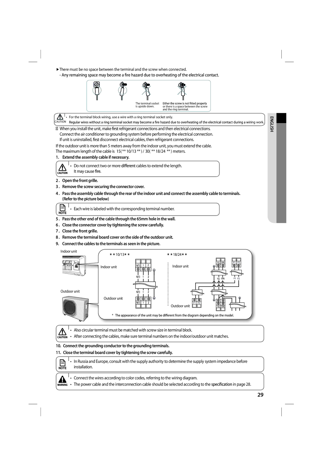
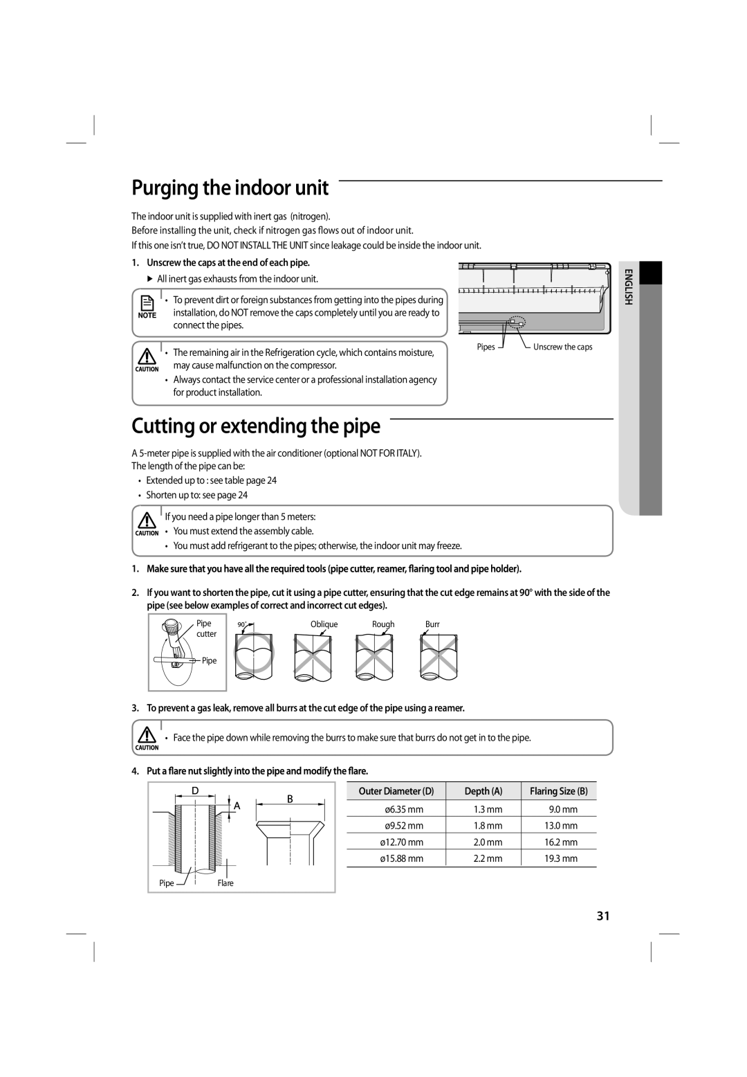
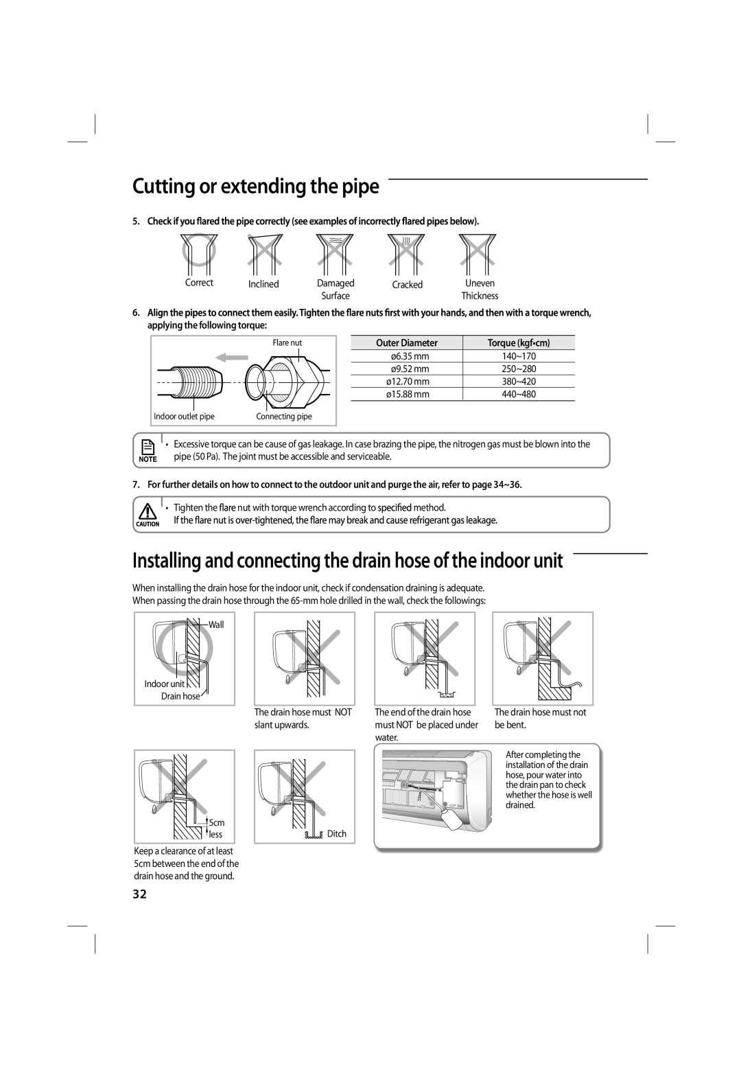
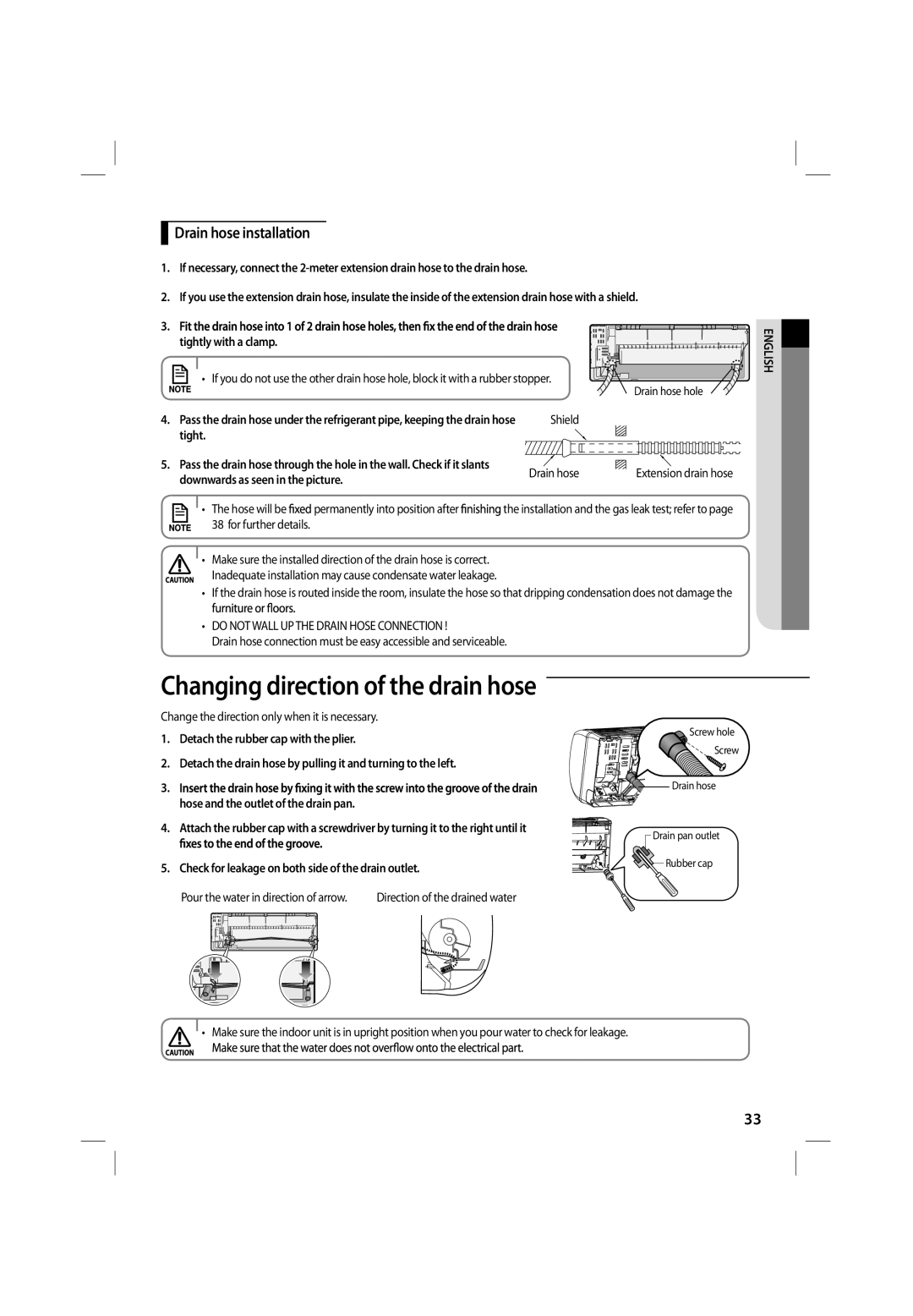
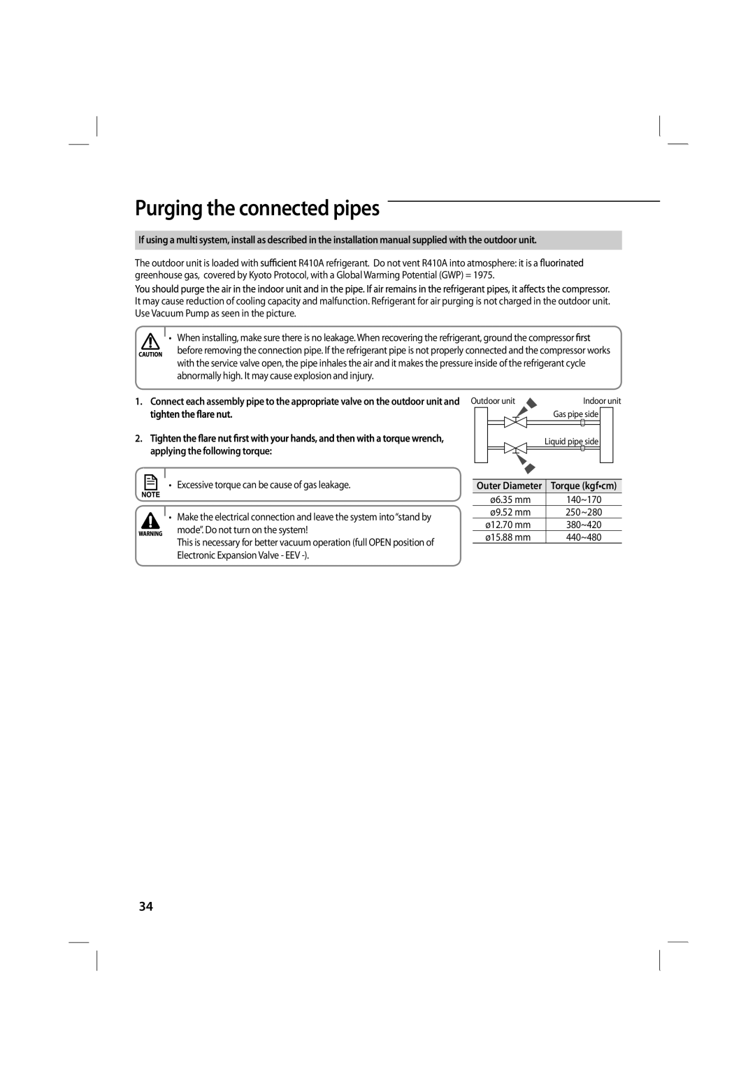
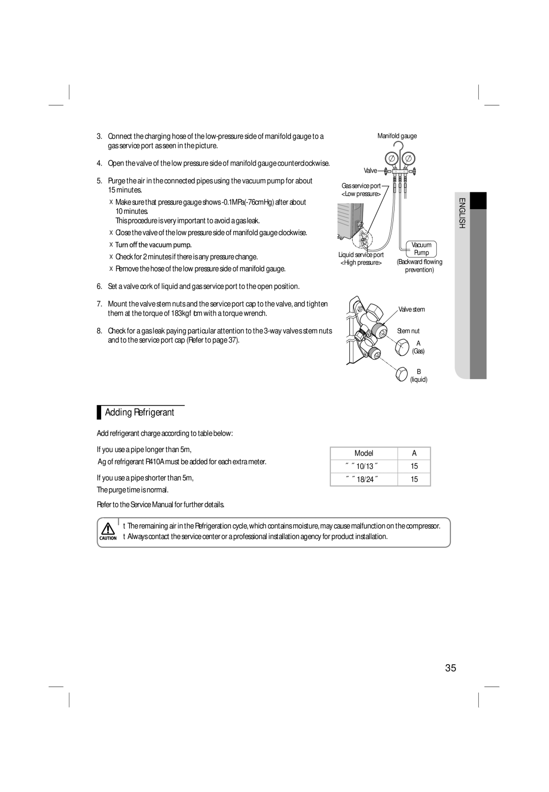
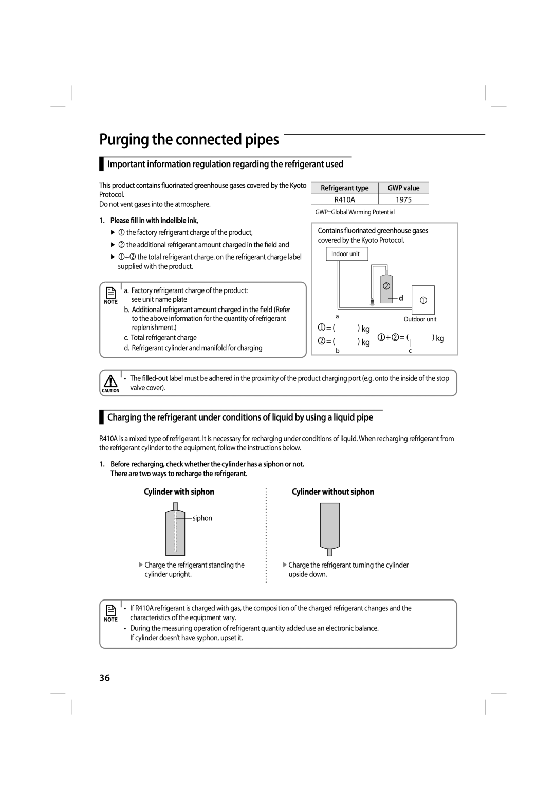
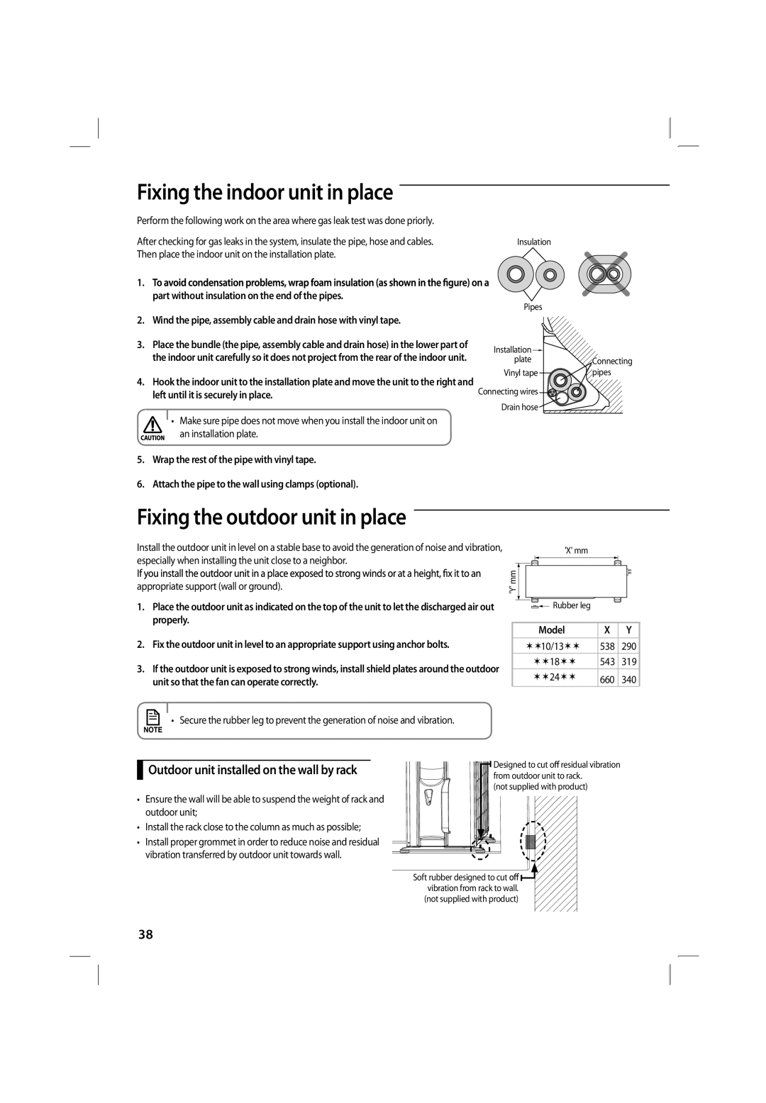
Image 30
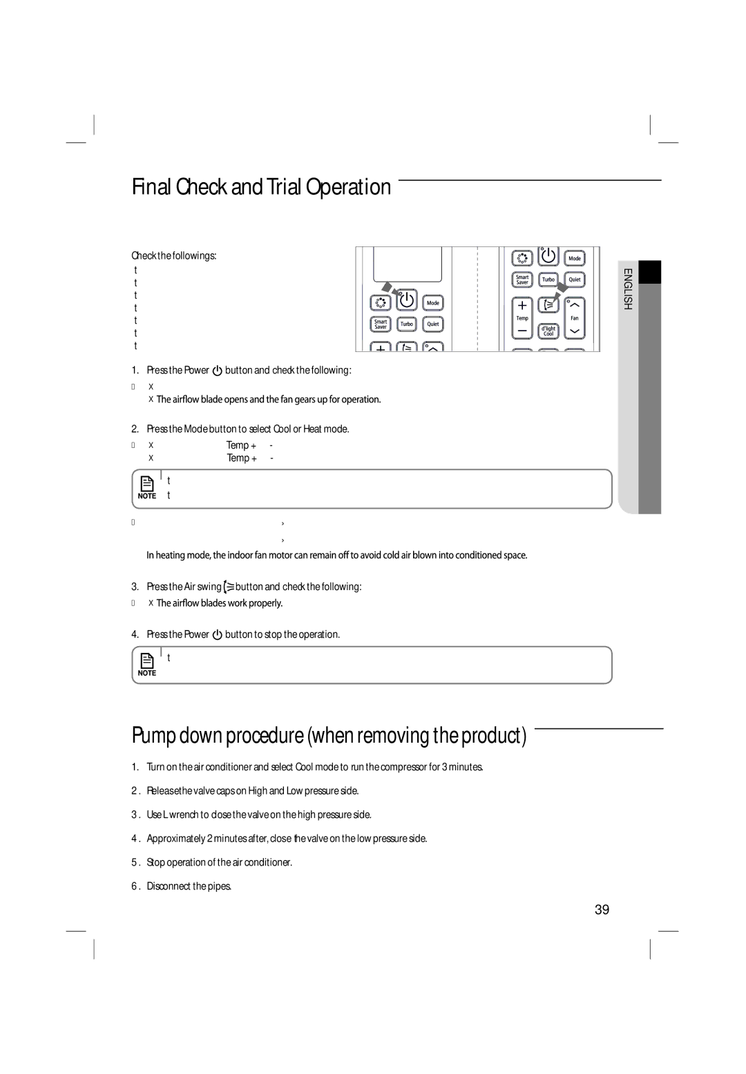
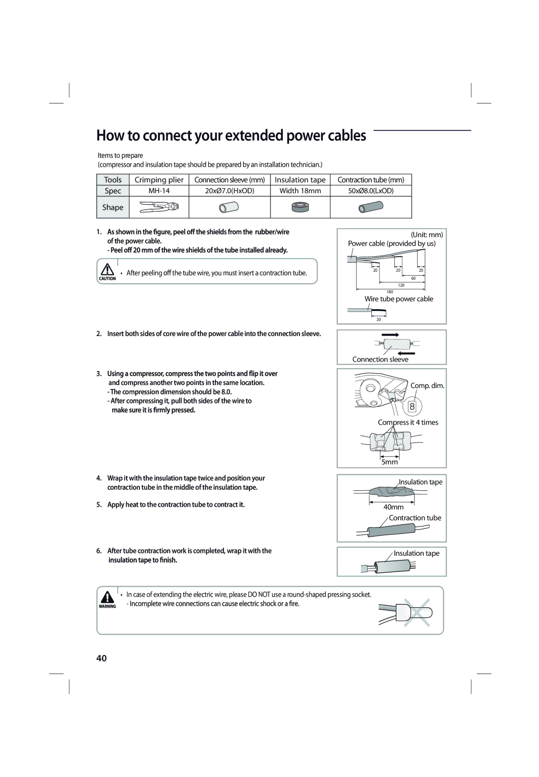
Contents Air Conditioner Contents Follow directions Safety precautionsImportant safety symbols and precautions Wall socketFor Using For Cleaning Checking before use Operation rangesMain parts Power buttonChecking the name of the parts DisplayChecking the remote controller Remote controller buttonsStoring the remote controller Remote controller displayBattery changing time Inserting the batteriesBasic function Button to adjust the temperature PressCirculate the air Using the Turbo functionPress the Air swing button on the remote controller Position you preferMode Press the Set/Cancel button to active it on Press the button Press the button to set the timeTimer 5 hours Using the Smart Saver functionTimer 1 hour From the moment you have set the timerUsing the Quiet function Opening the panel Cleaning the indoor unitCleaning the outdoor unit heat exchanger Heat exchangerSlide it down Cleaning the air conditionerClean the Air Dry the Ai lter in a ventilated areaMaintaining the air conditioner Periodical checksTroubleshooting Outdoor unit Heat exchanger during Heat mode in winter If may not be aConnection General information Model Name Included Models RemarkPower supply line, fuse or circuit breaker Choosing the installation locationInstalling the unit Won’t be considered in-warranty and charged to end userOutdoor Unit ModelWhen installing more than 1 outdoor unit  When the air outlet is towards the wallTop view Side view Accessories Accessories in the indoor unit caseAccessories in the outdoor unit case Tools required for installation General Tools Fixing the installation plateOptional accessories Tools for test operationsConnecting the assembly cable Connecting the cableFix the indoor unit Extend the assembly cable if necessary Each wire is labeled with the corresponding terminal numberSmooth the cut edges Then pull it out through the appropriate holeUnscrew the caps at the end of each pipe Purging the indoor unitCutting or extending the pipe Connect the pipesApplying the following torque Correct InclinedCracked Outer DiameterDrain hose installation Changing direction of the drain hosePurging the connected pipes Excessive torque can be cause of gas leakageAdding Refrigerant 1975 Covered by the Kyoto ProtocolTo check for gas leaks on the indoor unit Performing the gas leak testsTo check for gas leaks on the outdoor unit Leak test with nitrogen before opening valvesPart without insulation on the end of the pipes Outdoor unit installed on the wall by rackFixing the outdoor unit in place Properly ModelPress the Mode button to select Cool or Heat mode Pump down procedure when removing the productPress the Power button and check the following Final Check and Trial OperationHow to connect your extended power cables Questions or COMMENTS?