Quadra-Fire QV36-A, QV32-A manual Framing the Fireplace, Framing Dimensions

Page 13

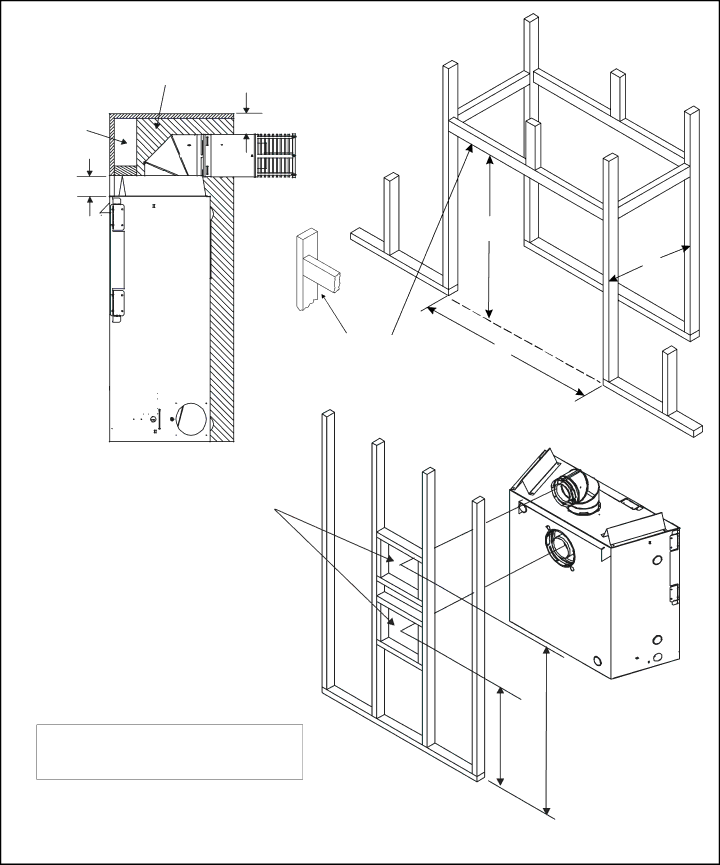
Step 2. Framing the Fireplace

Fireplace framing can be built before or after the fireplace is set in place. Framing should be positioned to accommo- date wall coverings and fireplace facing material. The dia- gram below shows framing reference dimensions.

CAUTION: MEASURE FIREPLACE DIMENSIONS AND VERIFY FRAMING METHODS AND WALL COVERING DETAILS BEFORE FRAMING.

NON-COMBUSTIBLE ZONE

IS DEFINED BY 3” ABOVE THE

ELBOW FOR THE ENTIRE

WIDTH AND DEPTH (BEHIND THE FRONT HEADER) OF THE FIREBOX.

WALL STUD

3 1/2”

3”

WARNING:

To ensure proper clearances the front framing header must be installed on its narrow edge and to the front of the frame.

B

A

C

Framing should be

VENT

FRAMING

constructed of 2 X 4

HOLE

lumber or heavier.


The framing headers may rest on the fireplace stand-offs.

*The center of the framing hole is one (1) inch (25.4mm) above the center of the horizontal vent pipe.

Model

A

B

C

D

E *

QV36-A

42”

38 1/4”

16 1/4”

41”

27 7/8”

QV32-A

37”

33”

16 1/4”

36 1/2”

24 3/8”

E D

u Figure 5. Framing Dimensions

13

Image 13
Contents What to do if you smell gas Installers GuideSafety and Warning Information Table of Contents Service Parts Standing Pilot Ignition / D’ALLUMAGE PAR Veilleuse Accessories / AccessoiresLog Set Assembly DF-36TS-BK High Altitude Installations Installation CodesAppliance Certification CertificationIntroducing the Village Collection Gas Fireplaces Pre-install PreparationANY Such Action MAY Possibly Cause a Fire Hazard Diagram of the QV36-A Diagram of the QV-32-A Locating the Fireplace Constructing the Fireplace ChaseClearance Requirements Framing the Fireplace Framing DimensionsDV-FLEX-10 47 3/4 Identifying Vent Components Installing the Vent SystemVent System Approvals Use SL D-Series components only Straight UP Vertical VentingUse D-Series components only Use SL D-Series components only Venting with Two 90 Elbows Natural GAS MAX. = 16 FT 4.8m V + V1 + H MAX. = 40 FT 12.2m Venting with Three 90 elbows Venting with Three 3 90 o Elbows + H 1 MAX. = 16 FT 4.8m + V 1 + H + H Venting with Four 90 elbows SET of Collars YOU are Using could Cause a Fire Continue Adding Vent Components Adding Venting Components Install Support BracketsCeiling Firestop Ceiling Side Positioned SO That the Arrow is Pointing UP Vent Termination191mm Minimum Trapezoid CAP TerminationVent Termination Minimum Clearances Minimum Height from Roof to Lowest Discharge Opening Gas Control System Positioning, Leveling, and Securing the FireplaceStanding Pilot Ignition System Gas Pressure Requirements Gas Supply LineTo Check for GAS Leaks PressureFor Standing Pilot Ignition Wiring Appliance Requirements Wiring the FireplaceOptional Accessories Wall SwitchFinishing Refractory Kit Placement BRICK-291, BRICK-293Glass Specifications Installing Trim, Logs Ember MaterialBefore Lighting the Fireplace Double-check for faulty componentsLighting the Appliance After the InstallationStanding Pilot Ignition What to do if YOU Smell GASImportant Turn OFF the GAS Before Servicing Your Fireplace Fireplace MaintenanceTroubleshooting Be Placed in this Opening Lifetime Warranty