Preparing the Site for the VCN Access Concentrator 13
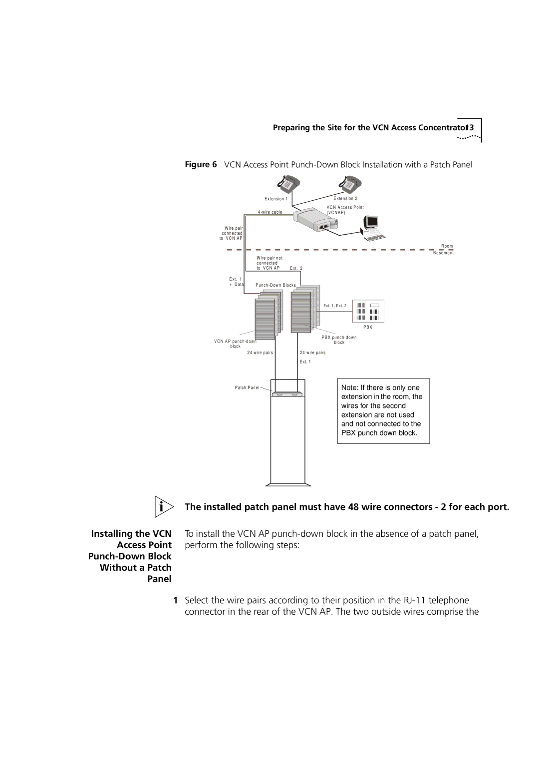
Figure 6 VCN Access Point Punch-Down Block Installation with a Patch Panel
E xtension 1
E xtension 2
V C N A ccess P oint ![]() (V C N A P)
(V C N A P)
W ire pair |
|
|
connected |
|
|
to V C N A P |
|
|
|
| R oom |
| W ire pair not | B asem ent |
|
| |
| connected |
|
| to V C N A P | E xt. 2 |
E xt. 1 |
|
|
+ D ata | P | |
Ext. 1, Ext. 2
| P B X |
V C N AP | P B X |
block | |
block |
|
24 w ire pairs | 24 w ire pairs |
| E xt. 1 |
P atch P anel | Note: If there is only one |
| extension in the room, the |
| wires for the second |
| extension are not used |
| and not connected to the |
| PBX punch down block. |
The installed patch panel must have 48 wire connectors - 2 for each port.
Installing the VCN To install the VCN AP
Punch-Down Block
Without a Patch
Panel
1Select the wire pairs according to their position in the
