Installing the VCN Access Concentrator 23
Front Panel Connections
Refer to “Preparing the Site for the VCN Access Concentrator” on page 10 before connecting the VCN AC to Ethernet switch through the front.
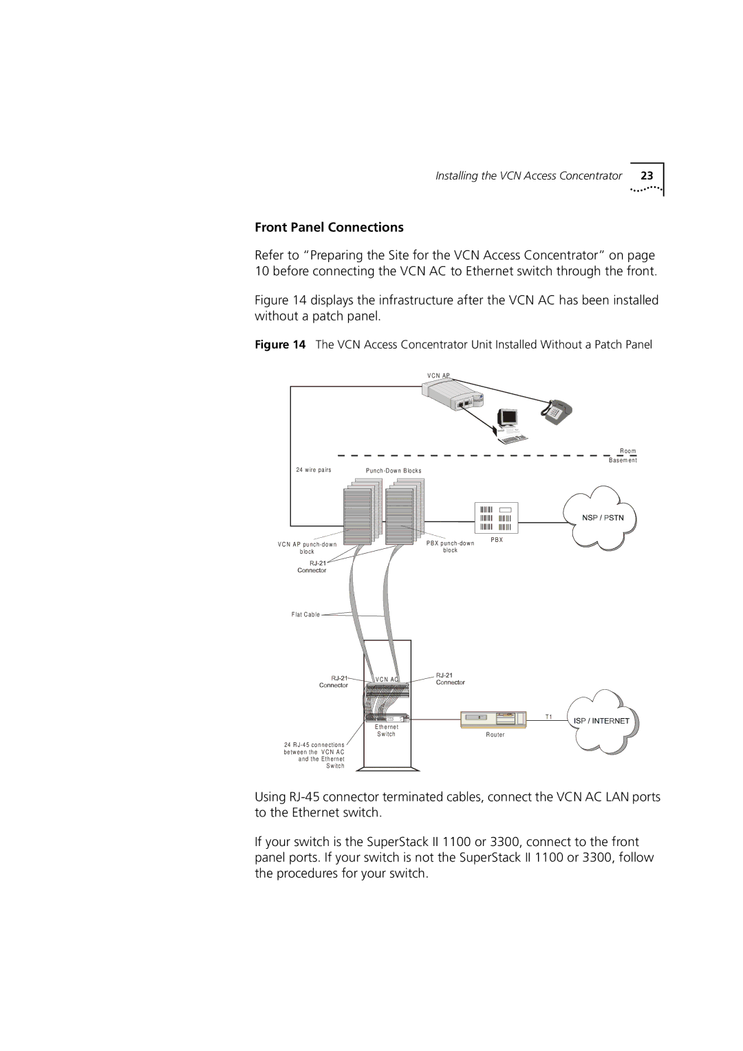
Figure 14 displays the infrastructure after the VCN AC has been installed without a patch panel.
Figure 14 The VCN Access Concentrator Unit Installed Without a Patch Panel
V C N AP
R oom
B asem ent
24 w ire pairs | P | |||||||
|
|
|
|
|
|
|
|
|
|
|
|
|
|
|
|
|
|
|
|
|
|
|
|
|
|
|
|
|
|
|
|
|
|
|
|
|
|
|
|
|
|
|
|
|
|
|
|
|
|
|
|
|
|
|
|
|
|
|
|
|
|
|
V C N AP
block
P B X
block
P B X
Flat C able ![]()
V C N AC
T1 |
E thernet |
|
S w itch | R outer |
24R
S w itch
Using
If your switch is the SuperStack II 1100 or 3300, connect to the front panel ports. If your switch is not the SuperStack II 1100 or 3300, follow the procedures for your switch.
