12Visitor and Community Network Access Concentrator Installation Guide
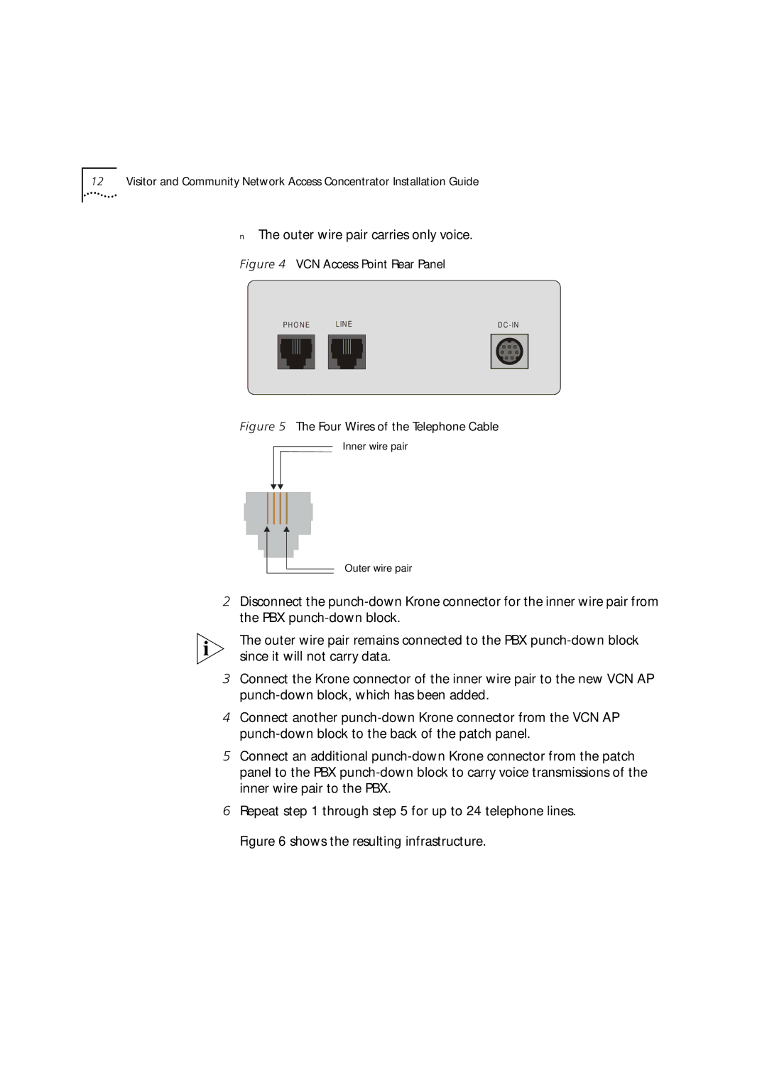
■The outer wire pair carries only voice.
Figure 4 VCN Access Point Rear Panel
| P H O N E |
| L IN E |
| D C | ||||
|
|
|
|
|
|
|
|
|
|
|
|
|
|
|
|
|
|
|
|
|
|
|
|
|
|
|
|
|
|
|
|
|
|
|
|
|
|
|
|
|
|
|
|
|
|
|
|
|
|
|
|
|
|
|
|
|
|
|
|
|
|
|
|
|
|
|
|
|
|
|
|
|
|
|
|
|
|
|
|
|
|
|
|
|
|
|
|
|
|
Figure 5 The Four Wires of the Telephone Cable
Inner wire pair
Outer wire pair
2Disconnect the
The outer wire pair remains connected to the PBX
3Connect the Krone connector of the inner wire pair to the new VCN AP
4Connect another
5Connect an additional
6Repeat step 1 through step 5 for up to 24 telephone lines. Figure 6 shows the resulting infrastructure.
