3M Accessories | 3M Library Security System |
|
|
4.123Mt Model 494 Locking Exit or
Entrance Gate
Description/Characteristics
The 3M Model 494 is designed to restrain patrons during an alarm. Gates are shipped from the factory to open with a clockwise rotation but may be modified to open with a counterclockwise rotation.
The locking mechanism is controlled by an alarm signal and power from the detection system.
When a strip is detected in the detection system and an alarm is created, the exit gate will lock in the closed position blocking patron travel through the exit corridor. The gate remains locked for the alarm period. If the gate is locked during an emergency, the gate arm can be forced open with a force of 15 - 25 lbs. [6,8 - 11,3 kg].
Gates are not available on the Detection System Model 3500.
Installation
Locking exit gates may be installed on either side of the detection system. For single corridor systems, the gate box may be located at the end of either panel. For dual corridor systems, two gates are required and the gate boxes must be located at the ends of the two outside panels.
The locking exit gate is designed to be installed by 3M factory trained service personnel.
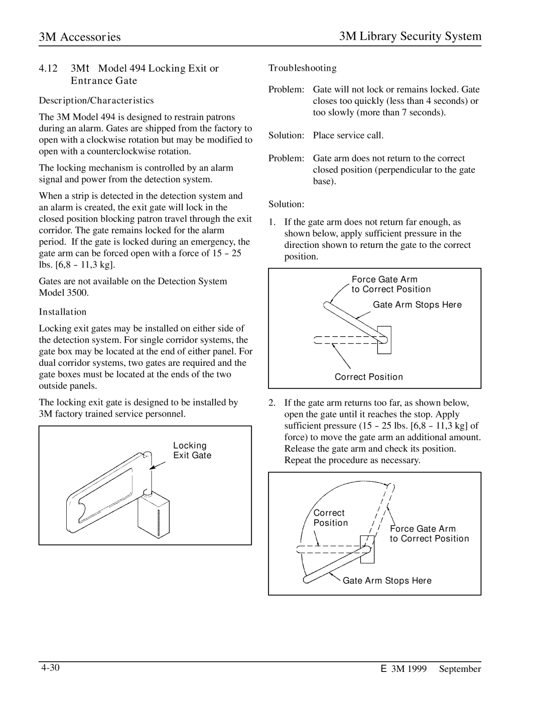
Locking
Exit Gate
Troubleshooting
Problem: Gate will not lock or remains locked. Gate closes too quickly (less than 4 seconds) or too slowly (more than 7 seconds).
Solution: Place service call.
Problem: Gate arm does not return to the correct closed position (perpendicular to the gate base).
Solution:
1.If the gate arm does not return far enough, as shown below, apply sufficient pressure in the direction shown to return the gate to the correct position.
Force Gate Arm to Correct Position
Gate Arm Stops Here
Correct Position
2.If the gate arm returns too far, as shown below, open the gate until it reaches the stop. Apply sufficient pressure (15 - 25 lbs. [6,8 - 11,3 kg] of force) to move the gate arm an additional amount. Release the gate arm and check its position. Repeat the procedure as necessary.
Correct Position
Force Gate Arm to Correct Position
Gate Arm Stops Here
E 3M 1999 September |