Manuals
/
Acer
/
Computer Equipment
/
Laptop
Acer
4730
manual
Connect the seven cables on the mainboard as shown
Models:
4730
1
122
194
194
Download
194 pages
34.55 Kb
119
120
121
122
123
124
125
126
Specifications
System Block Diagram
Bluetooth
Password
Euro symbol
Indicators
Dimension
Common Problems
Bios Setup Utility
Bios Flash Utility
Page 122
Image 122
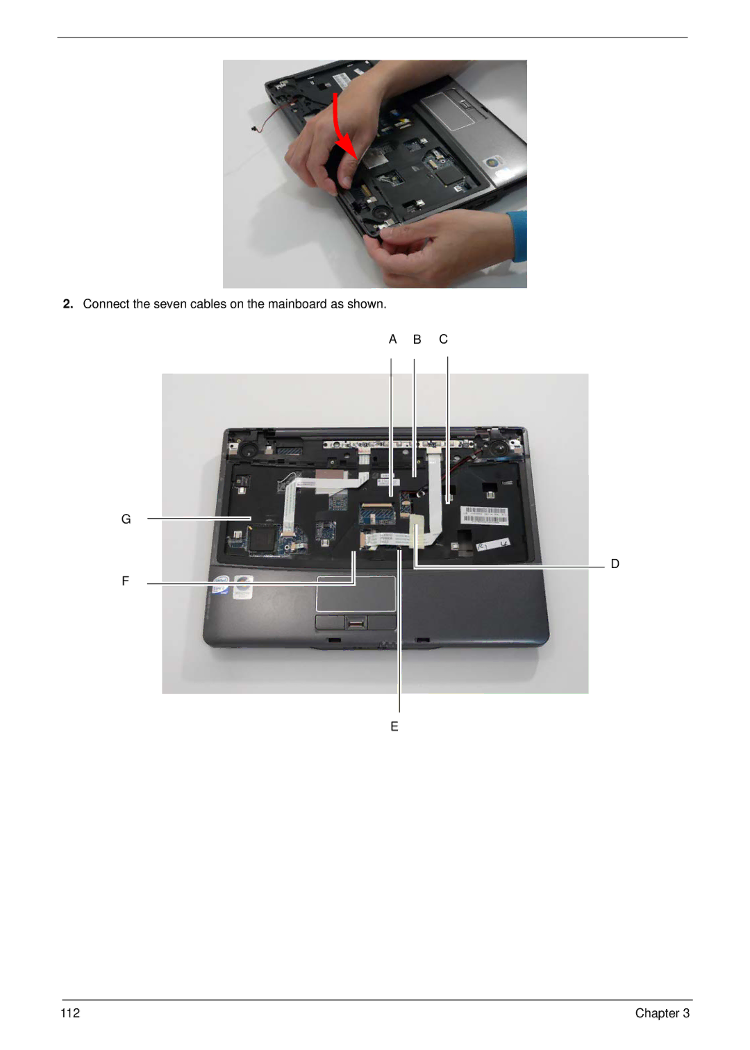
2.
Connect the seven cables on the mainboard as shown.
A B C
G
F
D
E
112
Chapter 3
Page 121
Page 123
Page 122
Image 122
Page 121
Page 123
Contents
TravelMate 4730/4730G Series Service Guide
Revision History
Copyright
III
Conventions
Preface
Page
Table of Contents
Table of Contents
TravelMate 4730/4730G Series
Microsoft Windows Vista Environment Test
Table of Contents
Features
Chapter
Communication
Dimensions and Weight
Power subsystem
Privacy control
Environment
System Block Diagram
Icon Description
Your Acer Notebook tour
Front View
Closed Front View
Left View
Hdmi
Right View
Rear View
Bottom View
Icon Function Description
Indicators
Easy-Launch Buttons
Wlan
Touchpad Basics with fingerprint reader
Function Left Button Right Button Main touchpad
Using the Keyboard
Lock Keys and embedded numeric keypad
Windows Keys
Key Description
Hot Keys
Hotkey Icon Function Description
US dollar sign
Euro symbol
Special Key
Using the System Utilities
Acer GridVista dual-display compatible
Page
Cache Specification
Hardware Specifications and Configurations
Processor Specification
2MB
0MB
System Memory Specification
Memory Combinations Slot Total Memory
Wireless Module 802.11b/g Specification
LAN Interface Specification
Bluetooth Interface Specification
WiFi/WiMAX Combo Module Specification
Video Memory Specification
Combo Drive Module Specification
Audio Interface Specification
USB Interface Specification
LCD Specification
Keyboard Specification
Battery Specification
ENE KB926
AC Adapter Specification
LCD Camera Specification
LCD Inverter Specification
System Power Management Specification
Chapter
Bios Setup Utility
Navigating the Bios Utility
Information
Parameter Description
Main
Parameter Description Format/Option
IDE
Advanced
Parameter Description Submenu Items
Aspm
Nfer
URR
FER
CER
Parameter Description Option
Enabled or
Security
Clear or Set
Setting a Password
Removing a Password
Changing a Password
DTS
Power
Emttm
Acpi S3
Boot
USB HDD
Exit
Exit Saving Changes
Bios Flash Utility
Chapter
Remove HDD/BIOS Utility
Remove HDD Password
Key in biospw 14452
Remove Bios Password
Chapter
Chapter
Machine Disassembly and Replacement
Disassembly Requirements
General Information
Pre-disassembly Instructions
Disassembly Process
Main Screw List Quantity Part Number
Screw List Step Quantity Color
External Module Disassembly Process
External Modules Disassembly Flowchart
Removing the Battery Pack
Removing the SD dummy card
Removing the NewCard dummy card
Removing the Lower Covers
Remove the Wlan cover as shown
Removing the Dimm Modules
Removing the Wlan Module
Step Size Quantity Screw Type Wlan Module M2*3 NL
Detach the Wlan board from the Wlan socket Chapter
Removing the Hard Disk Drive Module
Step Size Quantity Screw Type HDD Carrier M3*3.5 NL
Removing the Optical Drive Module
Step Size Quantity Screw Type ODD Module M2.5*5NL
Step Size Quantity Screw Type ODD Bracket M2*3 NL
Main Unit Disassembly Process
Removing the Switch Cover
Step Size Quantity Screw Type Switch Cover M2.5*3
Removing the Keyboard
Step Size Quantity Screw Type Keyboard M2*3
Removing the Power Board
Step Size Quantity Screw Type Power Board M2*3
Removing the Launch Board
Removing the Antenna
Step Size Quantity Screw Type Launch Board M2*3
Page
Removing the LCD Module
Step Size Quantity Screw Type LCD Module M2.5*8NL
Step Size Quantity Screw Type
Removing the Upper Cover
Step Size Quantity Screw Type Upper Cover M2.5x9
Chapter
Step Size Quantity Screw Type Upper Cover M2.5*9 NL
Chapter
Removing the Finger Print Reader
M2.5*3 NL
Chapter
Removing the Touch Pad Bracket
Removing the Left Speaker Module
Step Size Quantity Screw Type
Removing the Right Speaker Module
Removing the Bluetooth Module
Removing the Modem Module
Step Size Quantity Screw Type Modem Module M2*3 NL
Removing the Mainboard
Red Call out
Page
Removing the USB Board
Removing the RJ-11 Port
Removing the Thermal Module
Lift the Thermal Module clear of the Mainboard Chapter
Removing the CPU
Removing the VGA Module
Step Size Quantity Screw Type VGA Module M2*4-NI NL
LCD Module Disassembly Process
Removing the LCD Bezel
Step Size Quantity Screw Type LCD Bezel M2.5*5 NL
Removing the Inverter Board
Step Size Quantity Screw Type Inverter Board M2.5*6 NL
Removing the Camera Module
Step Size Quantity Screw Type Camera Board M2*2.3
Removing the LCD Panel
Removing the LCD Brackets and FPC Cable
Step Size Quantity Screw Type LCD Brackets M2*3 NL
Removing the Antennas
Removing the MIC Module
LCD Module Reassembly Procedure
Replacing the LCD Panel
Chapter
Page
100 Chapter
Replacing the LCD Bezel
Replacing the CPU
Main Module Reassembly Procedure
Replacing the VGA Module
Replacing the Thermal Module
Replacing the RJ-11 Port
Connect the RJ-11 cable to the modem module as shown
Replacing the Mainboard
Replacing the Modem Module
Replacing the USB Board
Replacing the Bluetooth Board
Replacing the Right Speaker Module
Replace the two securing screws
Replacing the Launch Board
Replacing the Finger Print Reader
Replacing the Touch Pad Bracket
Replacing the Left Speaker Module
Replacing the Upper Cover
Connect the seven cables on the mainboard as shown
Replacing the LCD Module
114 Chapter
Replacing the Antenna Cables
116 Chapter
Replacing the Switch Cover
Replacing the Keyboard
Turn the computer over and replace the five securing screws
Replacing the Wlan Module
Replacing the Hard Disk Drive Module
Replacing the Dimm Modules
Replacing the ODD Module
Replacing the Lower Covers
Replacing the NewCard and SD Card Trays
Common Problems
Symptoms Verified Go To
Power On Issue
Computer Shutsdown Intermittently
No Display Issue
No Post or Video
Random Loss of Bios Settings
Abnormal Video Display
LCD Failure
Built-In Keyboard Failure
Touchpad Failure
Internal Speaker Failure
Sound Problems
Internal Microphone Failure
Microphone Problems
Select Set up microphone
Select Startup Repair
HDD Not Operating Correctly
Select Repair your computer
ODD Failure
ODD Not Operating Correctly
Discs Do Not Play
Drive Not Detected
USB Failure Rightside
Modem Function Failure
Wireless/WiMAX Function Failure
Bluetooth Function Failure
Robson Module Failure
EasyTouch Button Failure
Fingerprint Reader Failure
Thermal Unit Failure
Hdmi Switch Failure
External Mouse Failure
Other Failures
Dimm
Intermittent Problems
Undetermined Problems
Driver Name Port Code
Post Codes Tables
Port 80 Post Codes
SNP
Driver Name Port80 Code
Before press function key
Post Keys and Messages
Key Function
Cpuid
Top View
Location Description
Bottom View
Steps for Clearing Bios Password Check
Clearing Password Check and Bios Recovery
Clearing Password Check
Hardware Open Gap Description
Bios Recovery Hotkey
Bios Recovery by Crisis Disk
Bios Recovery Boot Block
Steps for Bios Recovery by Crisis Disk
FRU Field Replaceable Unit List
TBD
TravelMate 4730/4730G Exploded Diagrams
Main Module
CPU TBD
LCD Module
TravelMate 4730/4730G FRU List
Half Mini Card 533ANHMWG-INTEL
VGA BOARD-NB9MGS256MB
Hdmi BOARD-UMA
Half Mini Card 512ANHMWG-INTEL
Power Cord AUS 3 PIN
Power Cord US 3 PIN
Power Cord EU 3 PIN
Power Cord UK 3 PIN
Mini Door
RAM Door
HDD Door for Dasp
Pcmcia Dummy Card
ODD BEZEL-COMBO
DVD/CDRW Combo Drive Toshiba TS-L463A
DVD/CDRW Combo Drive Sony CRX890S
ODD Bracket
HDD Sata 120G 5400RPM WD WD1200BEVS-22USTO
HDD Sata 120G 5400RPM Toshiba MK1246GSX
HDD Sata 120G 5400RPM Seagate ST9120817AS
HDD Sata 160G 5400RPM Toshiba MK1646GSX
Keyboard Belgian Black TM
Keyboard Inteui Black TM
Keyboard Arabic Black TM
Keyboard Brazilian Black TM
LCD BRACKET-R
LCD Cover ASSY-PLASTIC
LCD Bezel for CCD
LCD BRACKET-L
LCD Panel G 14.1 Wxga SAM LTN141W3-L01-J L6 LF
LCD Cover ASSY-MG
LCD Panel G 14.1 Wxga AUO B141EW04-V4 LF
Inverter
MB ASSY-UMA TBD MB ASSY-DIS CPU Support Bridge
CE6 RAM 512MB Ddrii 667 Hynix HYMP164S64CP6-Y5
RAM 512MB Ddrii 667 Nanya NT512T64UH8B0FN-3C
RAM 512MB Ddrii 667 Samsung M470T6464QZ3
RAM 1GB Ddrii 667 Nanya NT1GT64U8HB0BN-3C
Screw DIS-THE-SCREW
Screw List
Screw
Chapter 165
Appendix a
TravelMate 4730/4730G Series
Appendix a
Appendix a 168
Appendix a
Appendix a 170
NSM8XS TCS4E
Appendix a 172
942G25Mn
Appendix a 174
Test Compatible Components
Appendix B
Microsoft Windows Vista Environment Test
Memory Test
Vendor Type Description LAN Test
LCD Test
Modem Test
178
Online Support Information
Appendix C
180
Index
182
Wireless Function Failure 136 Wlan Board
184
Top
Page
Image
Contents