Manuals
/
Brands
/
Computer Equipment
/
Laptop
/
Acer
/
Computer Equipment
/
Laptop
Acer
5737Z
- page 46
1
46
188
188
Download
188 pages, 7.05 Mb
36
Chapter 2
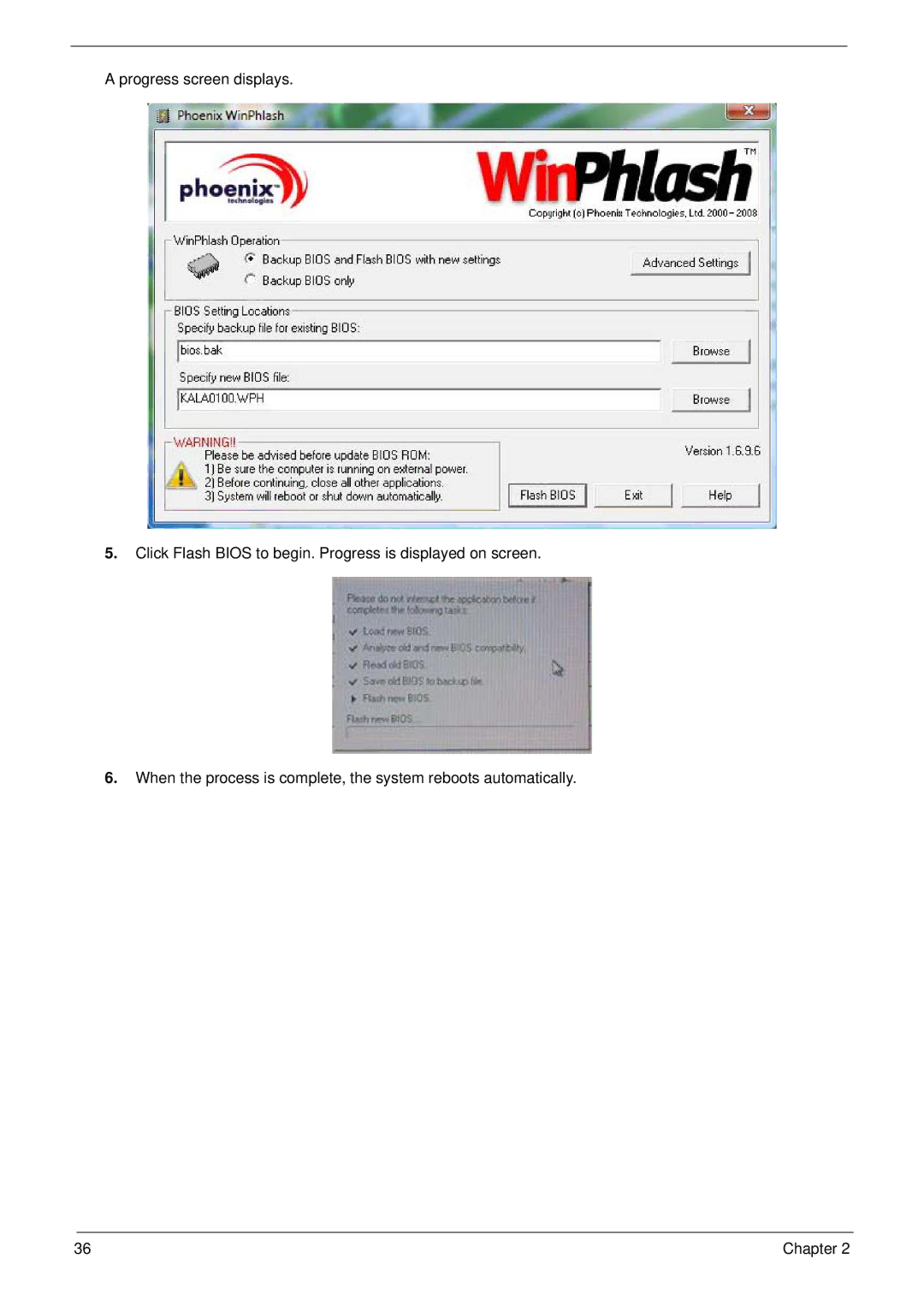
A progress screen displays.
5.
Click Flash BIOS to begin. Progress is displayed on screen.
6.
When the process
is complete, the system reboots automatically
.
Contents
Main
Page
Copyright
Disclaimer
Conventions
Preface
Page
System Specifications 1
System Utilities 23
Machine Disassembly and Replacement 41
Troubleshooting 119
Page
Page
System Specifications
Chapter 1
Features
Operating System
Platform
Dimensions and Weight
Communication
Privacy control
Power subsystem
Special keys and controls
Environment
4Chapter 1
System Block Diagram
Mobile Penryn
nVIDIA MCP79 (MX/MH)
Your Acer Notebook tour
Front View
Closed Front View
Rear View
Left View
Right View
Bottom View
Indicators
TouchPad Basics (with fingerprint reader)
Using the Keyboard
Lock Keys and embedded numeric keypad
Windows Keys
Hot Keys
Special Key
Using the System Utilities
Acer GridVista (dual-display compatible)
Hardware Specifications and Configurations
Page
Page
Page
Chapter 1 21
Super-Multi Drive Module
Audio Interface
Page
System Utilities
Chapter 2
BIOS Setup Utility
Navigating the BIOS Utility
Information
Main
Advanced
Security
Page
Page
Boot
Exit
BIOS Flash Utilities
DOS Flash Utility
Page
WinFlash Utility
Page
Remove HDD/BIOS Password Utilities
Page
Page
Using DMITools
Using the ICW50/ICY70 LAN MAC Utility
Machine Disassembly and Replacement
Chapter 3
Disassembly Requirements
General Information
Pre-disassembly Instructions
Disassembly Process
External Module Disassembly Process
External Modules Disassembly Flowchart
Page
Page
Removing the Lower Covers
Page
Page
Page
Page
Page
Page
Removing the WLAN Module
Page
Main Unit Disassembly Process
Main Unit Disassembly Flowchart
Removing the Switch Cover
Page
Page
Page
Page
Page
Page
Page
Page
Page
Removing the Upper Cover
Page
Page
Page
Page
Page
Page
Page
Page
Page
Page
Page
Removing the Thermal Module
Page
Page
LCD Module Disassembly Process
LCD Module Disassembly Flowchart
Removing the LCD Bezel
Page
Page
Page
Page
Page
Removing the LCD Brackets and FPC Cable
Page
Page
LCD Module Reassembly Procedure
Replacing the MIC and Antennas
Page
Replacing the LCD Panel
Page
Page
Main Module Reassembly Procedure
Replacing the CPU
Replacing the Thermal Module
Page
Page
Page
Page
Page
Page
Page
Page
Page
Page
Page
Page
Replacing the Function Board
Page
Page
Page
Page
Page
Replacing the Lower Covers
Page
Page
Troubleshooting
Chapter 4
Common Problems
Power On Issue
Computer Shutsdown Intermittently
No Display Issue
No POST or Video
Abnormal Video Display
Random Loss of BIOS Settings
Page
Page
Sound Problems
Internal Microphone Failure
Microphone Problems
HDD Not Operating Correctly
ODD Failure
ODD Not Operating Correctly
Discs Do Not Play
Discs Do Not Burn Properly
Playback is Choppy
Drive Not Detected
Drive Read Failure
Modem Function Failure
Wireless Function Failure
Thermal Unit Failure
External Mouse Failure
Other Failures
Intermittent Problems
Undetermined Problems
Post Codes
Chipset POST Codes
Page
Page
Page
Jumper and Connector Locations
Chapter 5
Top View
Page
Clearing Password Check and BIOS Recovery
Clearing Password Check
Hardware Open Gap Description
Steps for Clearing BIOS Password Check
BIOS Recovery by Crisis Disk
BIOS Recovery Boot Block:
BIOS Recovery Hotkey:
Steps for BIOS Recovery from USB Storage:
Steps for BIOS Recovery by Crisis Disk:
Page
FRU (Field Replaceable Unit) List
Chapter 6
Aspire 5737Z Series Exploded Diagrams
Main Assembly
LCD Panel
Aspire 5737Z Series FRU List
Page
Page
Page
Page
Page
Page
Page
Screw List
Page
Model Definition and Configuration
Appendix A
Aspire 5737Z Series
Page
Page
Page
Page
Page
Page
Page
Page
Page
Page
Page
Page
Test Compatible Components
Appendix B
Microsoft Windows Vista Environment Test
Page
Page
Online Support Information
Appendix C
Page
Index
A
B
E
C
M
N
O
P
S