Main Unit Disassembly Process
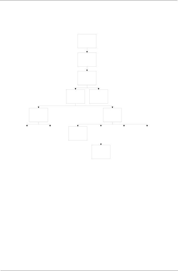
Main Unit Disassembly Flowchart
Remove External Modules before proceeding
Remove
Switch Cover
Remove
Keyboard
Remove
LCD Module
Remove
Launch Board
Remove
Upper Cover
Remove |
| Remove |
TouchPad |
| Left Speaker |
Bracket |
| Module |
|
|
|
Remove
USB Board
Remove
Lower Cover
Remove |
| Remove |
| Remove | |
| Right Speaker |
| |||
Mainboard |
|
| Bluetooth Module | ||
| Module |
| |||
|
|
|
|
| |
|
|
|
|
|
|
|
|
|
|
|
|
Remove
CPU
Screw List
Step | Screw | Quantity | Part No. |
|
|
|
|
Switch Cover | M2.5*3 | 1 | 86.AZ802.006 |
|
|
|
|
Function Board | M2.5*3 | 1 | 86.AZ802.006 |
|
|
|
|
LCD Module | M2.5*8 | 4 | 86.AZ802.007 |
|
|
|
|
| M2.5*6 | 2 | 86.AZ802.003 |
|
|
|
|
Upper Cover | M2.5*8 | 9 | 86.AZ802.007 |
|
|
|
|
| M2.5*6 | 10 | 86.AZ802.003 |
|
|
|
|
| M2.5*3 | 2 | 86.AZ802.006 |
|
|
|
|
TouchPad Bracket | M2*3 | 2 | 86.AZ802.002 |
|
|
|
|
Left Speaker | M2.5*3 | 2 | 86.AZ802.006 |
Module |
|
|
|
|
|
|
|
Right Speaker | M2.5*6 | 1 | 86.AZ802.003 |
Module |
|
|
|
USB Board | M2.5*6 | 1 | 86.AZ802.003 |
|
|
|
|
Mainboard | M2.5*6 | 3 | 86.AZ802.003 |
|
|
|
|
Thermal Module | CPU_SCREW_ | 4 | N/A |
| SPRIN |
|
|
|
|
|
|
Chapter 3 | 55 |
