 Rear Panel Controls and Connectors
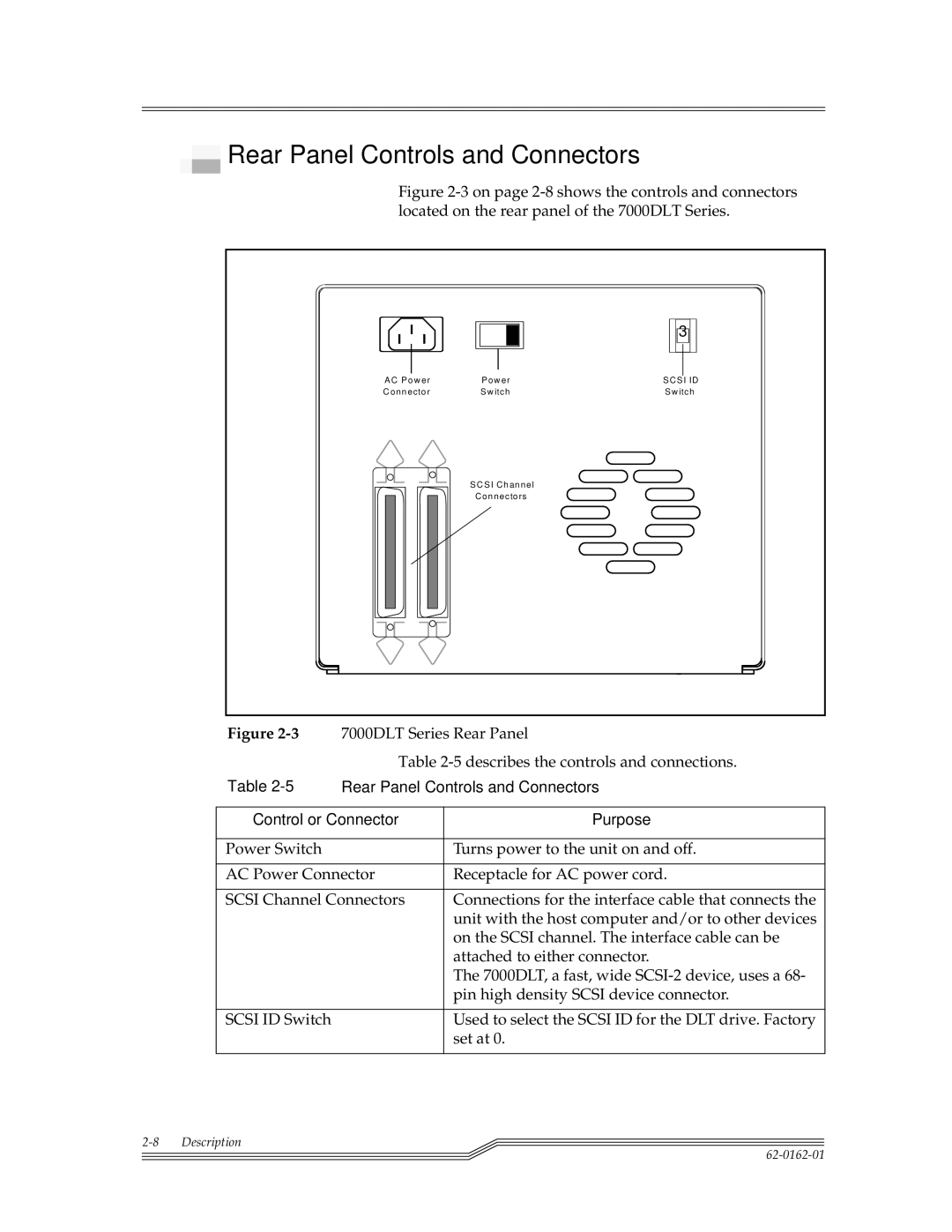
Figure 2-3 on page 2-8 shows the controls and connectors located on the rear panel of the 7000DLT Series.
|
| 3 |
A C P o w e r | P o w e r | S C S I ID |
C o n n e c to r | S w itc h | S w itc h |
| S C S I C h a n n e l |
|
| C o n n e c to rs |
|
Figure | 7000DLT Series Rear Panel | |
| Table | |
Table | Rear Panel Controls and Connectors | |
|
| |
Control or Connector | Purpose | |
|
|
|
Power Switch |
| Turns power to the unit on and off. |
|
| |
AC Power Connector | Receptacle for AC power cord. | |
|
| |
SCSI Channel Connectors | Connections for the interface cable that connects the | |
|
| unit with the host computer and/or to other devices |
|
| on the SCSI channel. The interface cable can be |
|
| attached to either connector. |
|
| The 7000DLT, a fast, wide |
|
| pin high density SCSI device connector. |
|
|
|
SCSI ID Switch |
| Used to select the SCSI ID for the DLT drive. Factory |
|
| set at 0. |
|
|
|
