TDU 120e
Trademarks
Save These Important Safety Instructions
Important Safety Instructions
REN/SOC FIC Usoc
Affidavit Requirements for Connection to Digital Services
Page
Vii
Canadian Emissions Requirements
Canadian Equipment Limitations
Limited Product Warranty
Customer Service, Product Support Information, and Training
Presales Inquiries and Applications Support
Post-Sale Support
Repair and Return
Training
Table of Contents
Operation
Status Menu
Configuration Menu
Port Configuration Port Config Nx/DBU 0.1 Menu Items
Remote/Management Menus
Xmodem
Table of Contents
List of Figures
Bridge, PBX, Video Conferencing Application Set-up
List of Figures Xxii
List of Tables
List of Tables Xxiv
Introduction
TDU 120e Overview
Introduction
Standard Features in the TDU 120e
OCU DP
TDU 120e Option Modules
DSX-1
DSU DP
Option Module Architecture
TDU 120e Option Modules
TDU 120e Configuration Applications
Router, PBX, Video Conferencing Application
Receipt Inspection
Installation
UNPACK, INSPECT, Power UP
Adtran Shipments
DC Powered Units
Power Connection
AC Powered Units
Customer Provides
Grounding Instructions
Installation
Identification of Rear Panel Layout
TDU 120e Rear Panels
TDU 120e Interfaces
Network Interface
Control In Port
External Alarm Connector
DS-1 PBX Interface
Craft Port
Power UP Testing
Self-Test
Set Unit Identification
Initialization
Set User Passcode
Set Control Port
Chain In PC
Chain In/Chain Out
Normal POWER-UP Procedure
Installation
Operation
Menu Operation
Main Menu
Sample Terminal Screen with TDU 120e Menu
General Menu Traversal
Select and Activate a Menu Item
Step Action Result
Example of Basic Menu Travel
Data Port Identification
Edit the Data Field
Exit Any Menu Field Operation or Display
Menu Structure
Telnet/Terminal Main Menu
Menu Options
Flash Download
Management Configuration
Front Panel
Quit Session
Craft Port
ACO Switch
Remote LED
Network Monitor Jack
LEDs
LED
Port 1.1 Option Card Monitor Jacks
Port Status LEDs
Watch PRO Adtran PC Program
Setting up the TDU 120e to Work over a LAN
Alternate Methods of Control
Step Action
Setting up the TDU 120e to Work over an EIA-232 Connection
Snmp
Status Menu
Status
SES
Where Means
Network NI Performance Reports
UAS
Network Interface NI Errors
Active Alarms
View History
Port Status
Nx/DBU 0.1 Menu Items DTE Data/Clock
DTE Status
DTE Port Rate
DBU Data/CNTRL
DBU Control
DBU Status
DS-1 0.2 Menu Items DS-1 Errors
Remote Port
Slip
LNK
Clear Port Alarm
Ethernet Status
CPU
Configuration Menu
Config
TDU 120e Config Menu Tree
Network NI Menu Tree
Unit Menu Tree
Network NI
Network NI Menu Items
Timing Mode
Network Timed
Network Timed Clock Source
Base DS-1
Base DS-1 Timed Clock Source
Base DTE Timing
Base DTE Timed Clock Source
Internal Timing
Internal Clock Source
Secondary Timing
Secondary Clock Source
Normal CSU Timing
Normal CSU
Alarm Report
ATT & FT1, Reject ALL
BPV Threshold
Alarm Format
Unit Menu
Exit
IP Address
Default Router
Control Port
Subnet Address
Map Exchange
OFF
Auto
DS0 Map a
Map In Use
DS0 Map a and DS0 Map B
DS0 Map B
DS0 Maps Configuration Menu
10. DS0 Temp Map
Initializing the Temp Map
Creating a DSO Map
Step Explanation
If you want to Enter selections
Applying the Temp Map
Editing the Temp Map
Step Action Explanation
Copying Map
Reviewing Maps
Copy Map a B to Temp Map
Create Temp Map
Review Temp Map
Port Configuration Port Config
Review Map a B
Edit Temp Map
Nx56/64 Config
Nx/DBU 0.1 Menu Items
Inhib
Backup Mode
Normal Mode of Operation
Dial Backup Config
Backup On
Retry Delay
Backup Delay
Restore Delay
Pattern Verify
Backup Testing
Wkend Lockout
DS-1 0.2 Menu Items
Trap in DBU
Inband Lpback
Robbed Bit Signaling
RBS Start
RBS End
Configuration Menu
Utility Menu
Util
If you want to Do this
Factory Restore
Time/Date
Press Escape
Change/Set a Passcode
Set Passcode
Unit ID
Lost Passcode
MAC Address
Software Revision
Port Utility
To Set the Unit Identification
Test Menu
Test
Network Tests
Loopback Tests
TDU 120e
Ansi FDL PLB
Ansi FDL LLB
Ansi FT1 LLB
Qrss Pattern
Test Patterns All Ones
All Zeros
Qrss All DS0s
Instructions for Generating a Qrss Test Pattern Step Action
Qrss TST DS0s
None
Pattern Result
How to Run an End-to-End Test on Fractional DS0s Step Action
Sync
Run Self-Test
Test Name What it does
Port Tests
DTE Loopback
Results
REM V.54
Pattrn
DBU Loopback
DBU TST Result
Cancel Tests
DBU DATA/CNTRL
Port Loopback
Test Menu
Remote Menu Access
Management Configuration
Remote/Management Menus
Unit Access Table
Unit Access Table
Unit Access Table Commands
Command What it does
Snmp Trap Community
Snmp Read Community
Snmp Read/Write Community
Host 1 Trap IP Address
Host 4 Trap IP Address
Host 2 Trap IP Address
Host 3 Trap IP Address
System Name
Flash Download
Xmodem
Tftp Server IP Address
Begin Firmware update
Quit Session
Tftp Server File name T120e.biz
Remote/Management Menus
Basic Components of Snmp
What is SNMP?
Appendix a Understanding Snmp
Network Manager
GetRequest
Commands
MIB
GetNextRequest
Message
GetResponse
Trap
TDU 120e Snmp Access
Snmp Trap Configuration
Snmp MIB Browser Configuration
RFC1406.MIB
Snmp MIB Files
Appendix A. Understanding Snmp
Appendix B Connector Pinouts
Wiring
Network
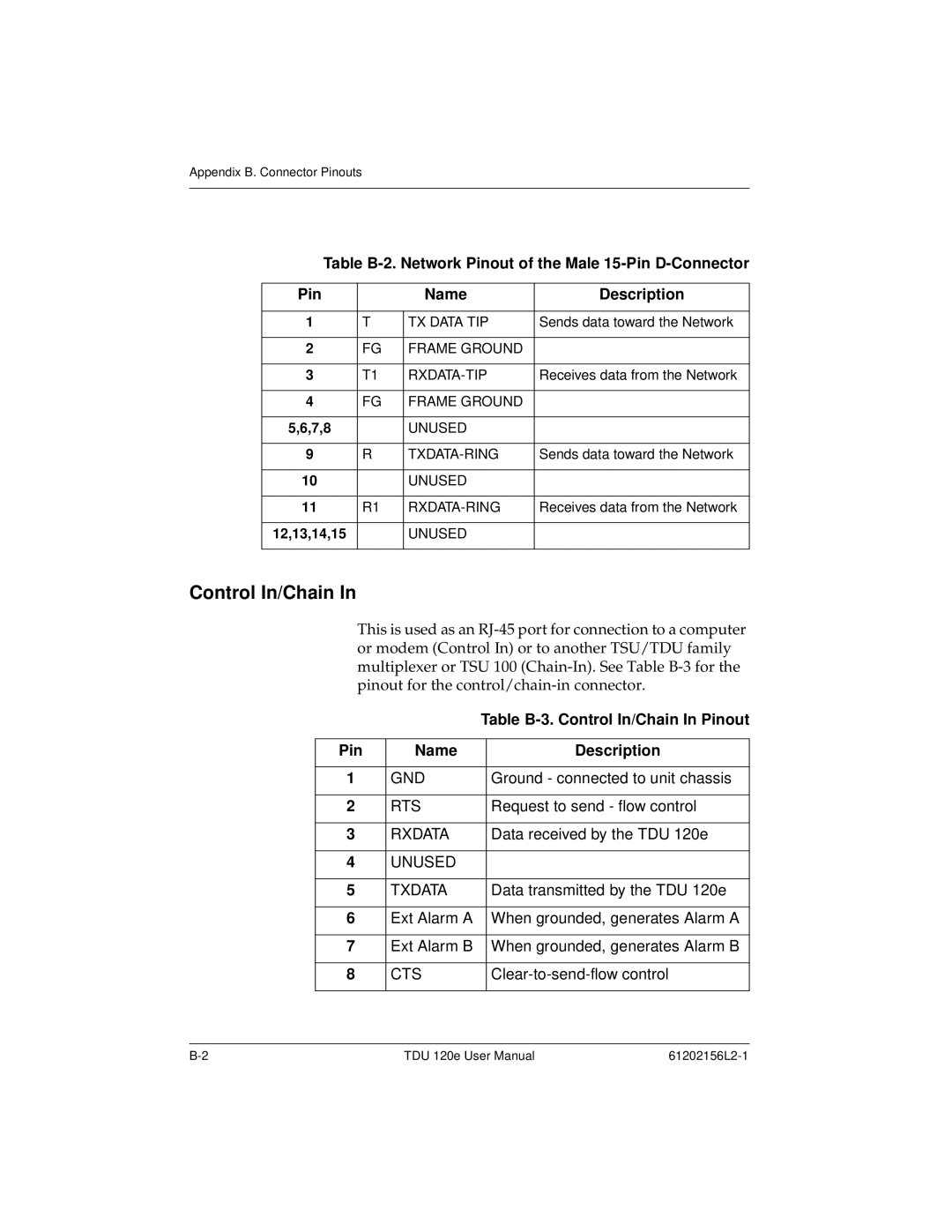
Control In/Chain
Pin Name Description
Control-Out/Chain-Out
Table B-4. Chain-Out Pinout
Table B-5. Craft Port Pinout
Nx56/64 DTE
Table B-6. V.35 Pinout for Nx56/64 DTE
Pin
Base DS-1 PBX
12,13,14,15
Alarm
Power
10BaseT
Network Interface NI
Alarm Messages
Appendix C System Messages
Nx/DBU Interface
Fifo Alarm
PLL Alarm
Zeros Alarm
DS-1 PBX Interface
Status Messages
Line Loop Up
Pattern Off
Frame Slip
Port Loop Up
Appendix D Specifications
Electrical Specifications
T1/FT1 Interface
Nx/DBU Interface Port 0.1-Nx56/64 V.35 Interface
CTS, DCD, DSR
DS-1 Interface Port
Management Interfaces
Rate
Receiver
Option Slot Interface
Chassis Specification
Environmental Specifications
Index
Numerics
Index
61202156L2-1 Index-3
Index-4