INSTALLATION
Check the appliance is electrically safe and gas sound when you have finished.
|
| ||
WARNING! | 2 | ||
3 | |||
| 1 | ||
The range MUST be secured by the |
|
| |
supplied. Unless properly installed, the range could |
| 3 | |
be tipped by leaning on the door and injury might |
|
| |
result from spilled hot liquids or from the range |
|
| |
itself. |
|
|
Note: The range must be set to the correct height and leveled before the
Kit Contents: |
| |
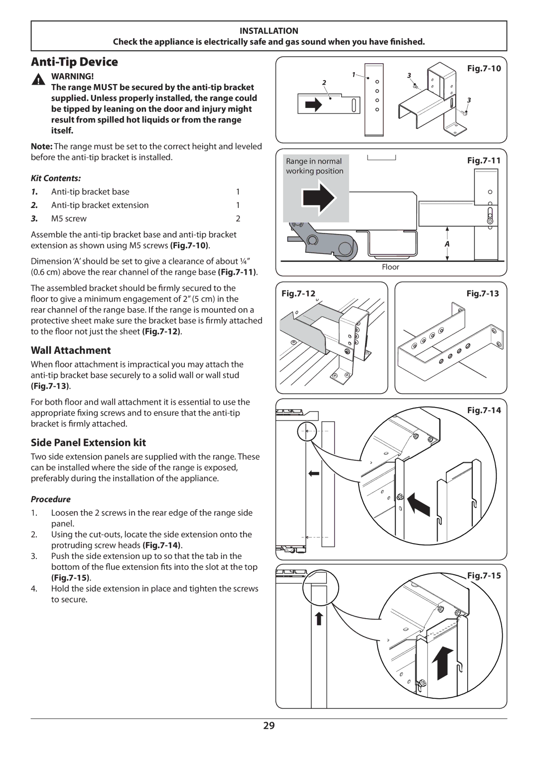
1. | 1 | |
2. | 1 | |
3. | M5 screw | 2 |
Assemble the
Dimension ‘A’ should be set to give a clearance of about ¼”
(0.6 cm) above the rear channel of the range base
The assembled bracket should be firmly secured to the floor to give a minimum engagement of 2’’ (5 cm) in the rear channel of the range base. If the range is mounted on a protective sheet make sure the bracket base is firmly attached to the floor not just the sheet
Wall Attachment
When floor attachment is impractical you may attach the
For both floor and wall attachment it is essential to use the appropriate fixing screws and to ensure that the
Side Panel Extension kit
Two side extension panels are supplied with the range. These can be installed where the side of the range is exposed, preferably during the installation of the appliance.
Procedure
1.Loosen the 2 screws in the rear edge of the range side panel.
2.Using the
3.Push the side extension up to so that the tab in the bottom of the flue extension fits into the slot at the top
4.Hold the side extension in place and tighten the screws to secure.
Range in normal | |
working position | |
| |
| A |
| Floor |
![]() Fig.7-15
Fig.7-15
29