analyzer cards together to create
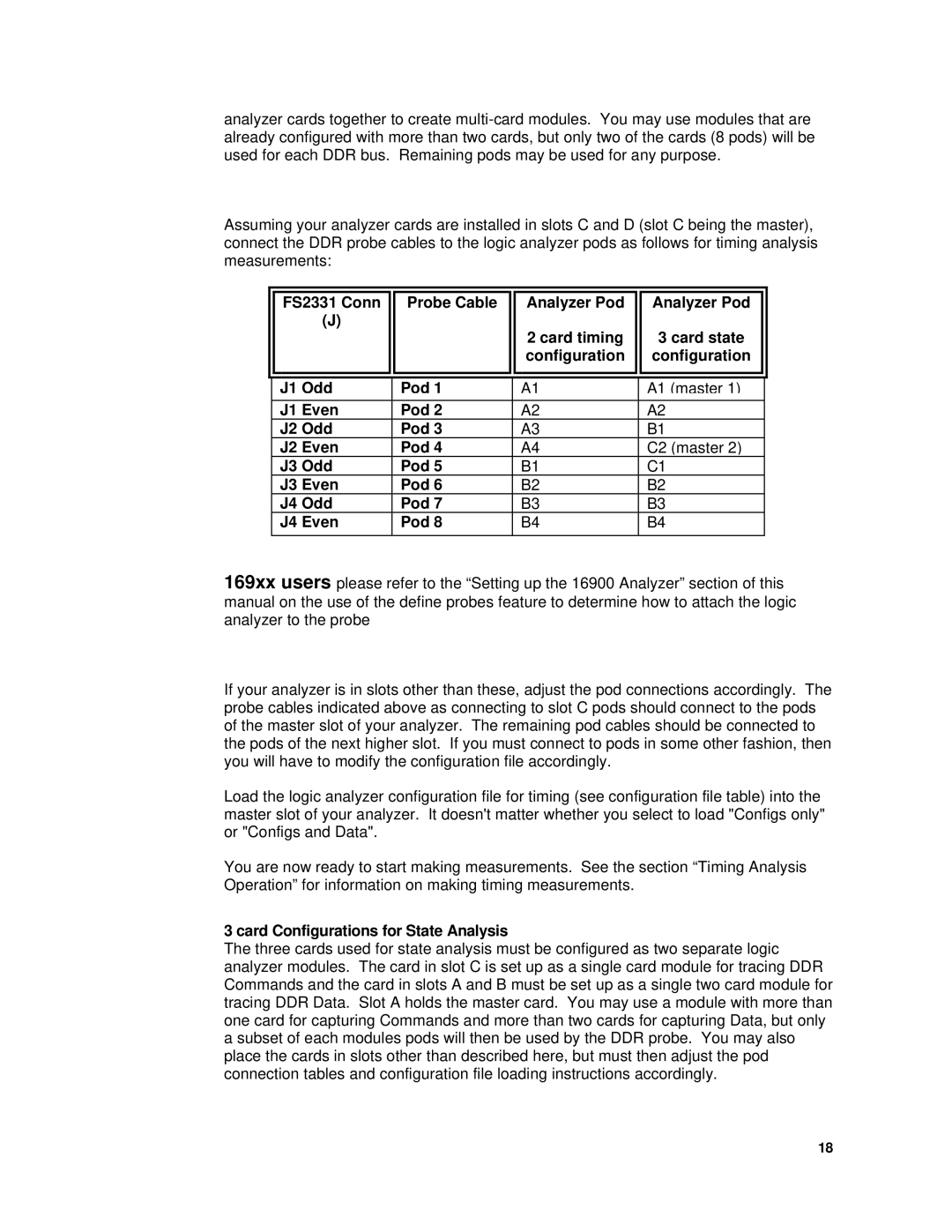
Assuming your analyzer cards are installed in slots C and D (slot C being the master), connect the DDR probe cables to the logic analyzer pods as follows for timing analysis measurements:
|
|
|
|
|
|
|
| FS2331 Conn | Probe Cable | Analyzer Pod | Analyzer Pod |
|
| (J) |
| 2 card timing | 3 card state |
|
|
|
| ||
|
|
|
| configuration | configuration |
|
|
|
|
|
|
|
|
|
|
|
|
|
| J1 Odd | Pod 1 | A1 | A1 (master 1) |
|
|
|
|
|
|
|
| J1 Even | Pod 2 | A2 | A2 |
|
| J2 Odd | Pod 3 | A3 | B1 |
|
| J2 Even | Pod 4 | A4 | C2 (master 2) |
|
| J3 Odd | Pod 5 | B1 | C1 |
|
| J3 Even | Pod 6 | B2 | B2 |
|
| J4 Odd | Pod 7 | B3 | B3 |
|
| J4 Even | Pod 8 | B4 | B4 |
|
|
|
|
|
|
169xx users please refer to the “Setting up the 16900 Analyzer” section of this manual on the use of the define probes feature to determine how to attach the logic analyzer to the probe
If your analyzer is in slots other than these, adjust the pod connections accordingly. The probe cables indicated above as connecting to slot C pods should connect to the pods of the master slot of your analyzer. The remaining pod cables should be connected to the pods of the next higher slot. If you must connect to pods in some other fashion, then you will have to modify the configuration file accordingly.
Load the logic analyzer configuration file for timing (see configuration file table) into the master slot of your analyzer. It doesn't matter whether you select to load "Configs only" or "Configs and Data".
You are now ready to start making measurements. See the section “Timing Analysis Operation” for information on making timing measurements.
3 card Configurations for State Analysis
The three cards used for state analysis must be configured as two separate logic analyzer modules. The card in slot C is set up as a single card module for tracing DDR Commands and the card in slots A and B must be set up as a single two card module for tracing DDR Data. Slot A holds the master card. You may use a module with more than one card for capturing Commands and more than two cards for capturing Data, but only a subset of each modules pods will then be used by the DDR probe. You may also place the cards in slots other than described here, but must then adjust the pod connection tables and configuration file loading instructions accordingly.
18