indicating its nominal delay value in 100ps units. Thus a 1700ps delay line will be marked “1705” and a 1200ps elayd line will be marked “1205”. The delay lines are accurate to within +/- 50ps)
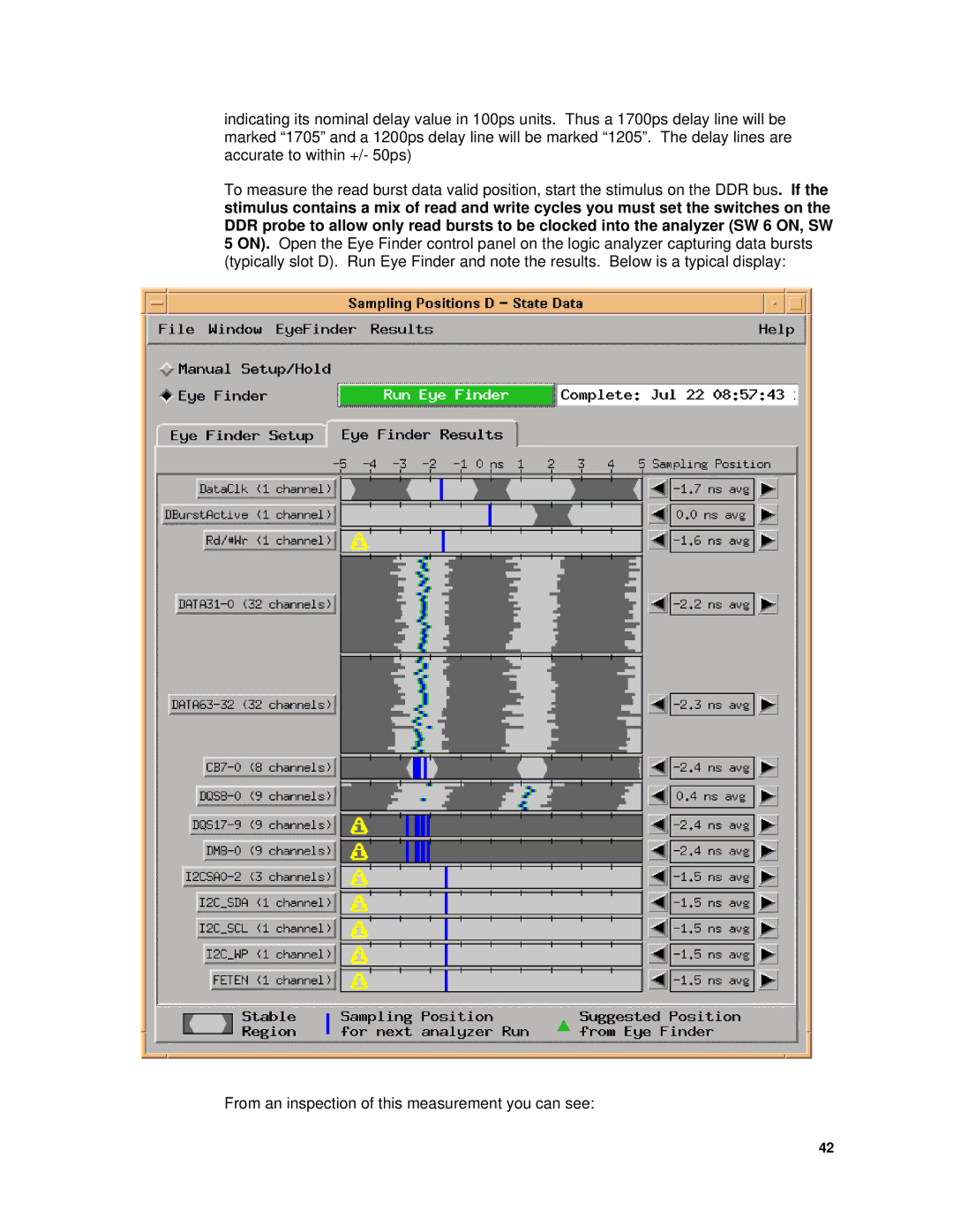
To measure the read burst data valid position, start the stimulus on the DDR bus. If the stimulus contains a mix of read and write cycles you must set the switches on the DDR probe to allow only read bursts to be clocked into the analyzer (SW 6 ON, SW 5 ON). Open the Eye Finder control panel on the logic analyzer capturing data bursts (typically slot D). Run Eye Finder and note the results. Below is a typical display:
From an inspection of this measurement you can see:
42