7.5 I/O Terminal Application
Typically used in association with programming scripts for developing applications for motion detection, event triggering, alarm notification via
Connector Pin Assignment
PIN No. | FUNCTION | SPECIFICATION |
1 | Compliant to | |
2 |
| |
3 | Active High voltage 9~40VDC | |
4 | Dropout voltage 0 VDC | |
5 | Close circuit current maximum | |
| (Normal Open) | 70 mAAC, or 100 mADC. |
6 | Output resistance 30 Ohm. | |
| (Common) | Open circuit voltage maximum |
|
| 240VAC or 350VDC |
Monitoring and Controlling
By entering http requests in your browser’s URL field, you can:
‧Monitor the status of digital input
‧Drive the output switch on or off
‧Control the speed/position of pan/tilt/zoom motors in a swivel stand or a speed dome camera.
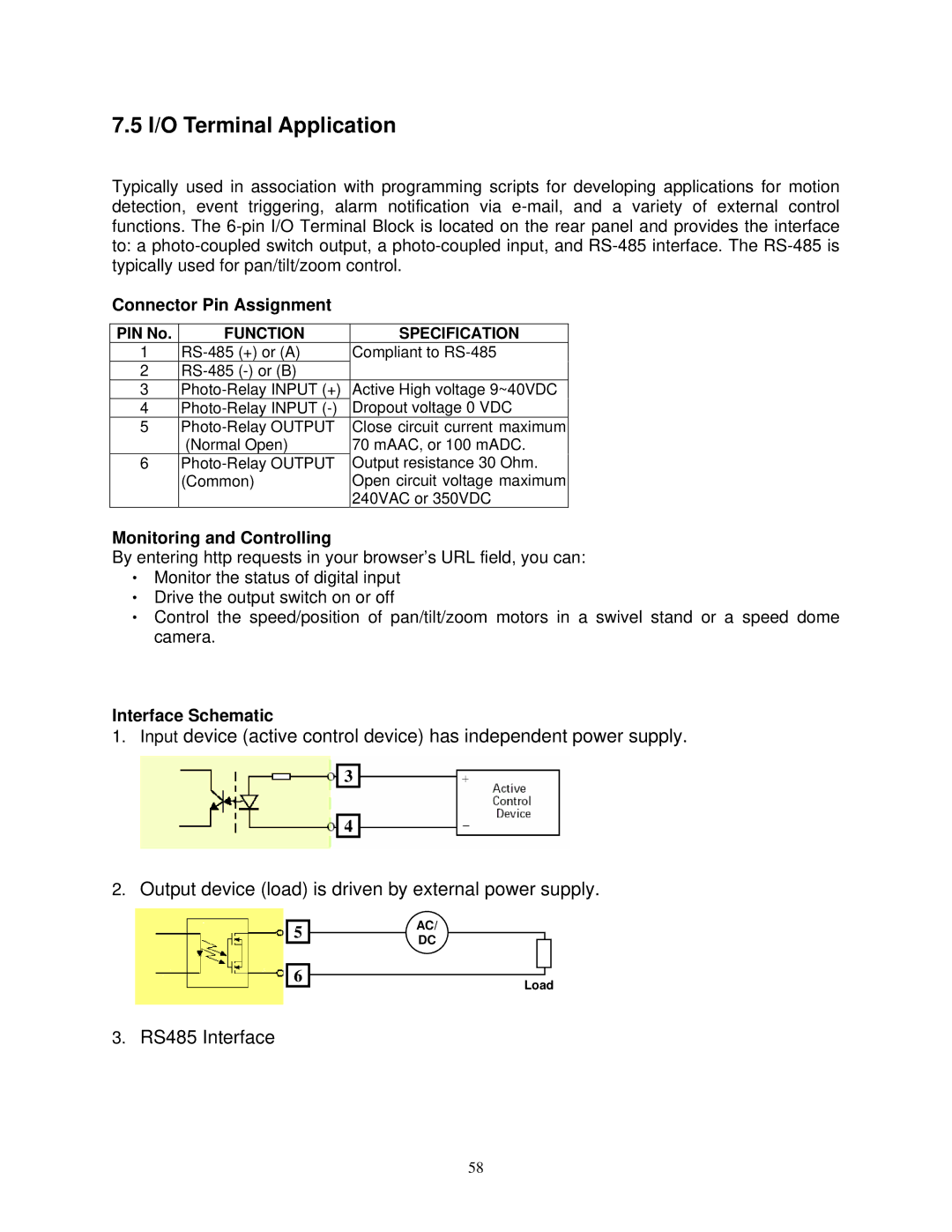
Interface Schematic
1. | Input device (active control device) has independent power supply. |
| 3 |
| 4 |
2. | Output device (load) is driven by external power supply. |
5 |
6 |
AC/
DC
Load
3.RS485 Interface
58