Manuals
/
Alamo
/
Lawn and Garden
/
Lawn Mower
Alamo
803350C
manual
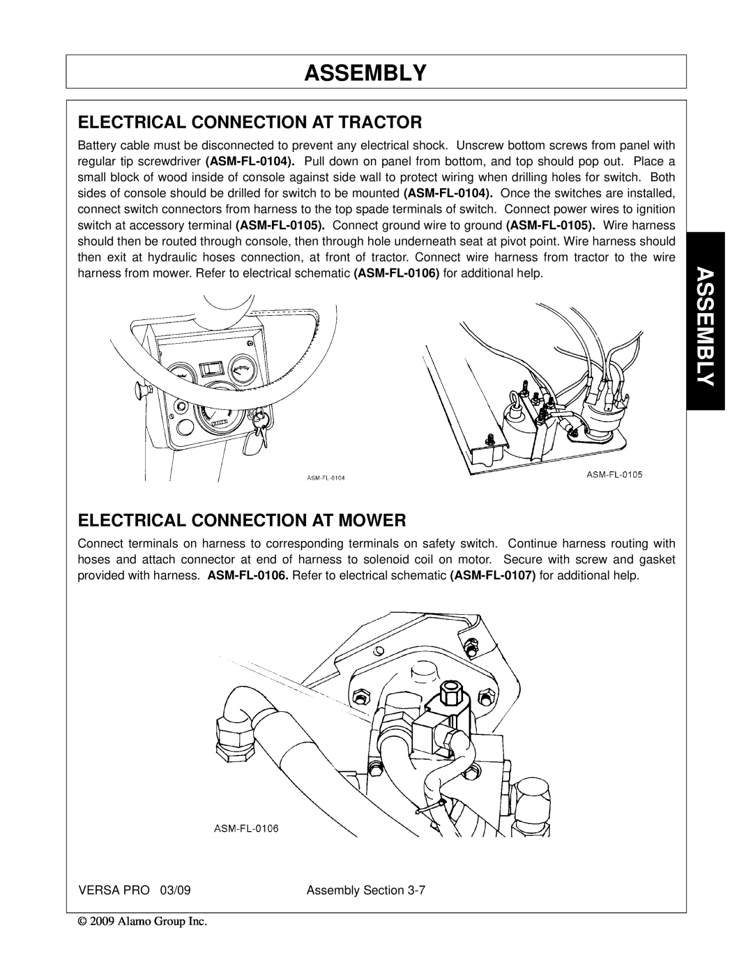
Electrical Connection At Tractor, Electrical Connection At Mower, Assembly
Models:
803350C
1
91
168
168
Download
168 pages
22.47 Kb
88
89
90
91
92
93
94
95
Troubleshooting
Specs
Install
Hour Lubrication Chart
Warranty
Maintenance
Assembly Section
Engagement Check Procedure
Roller Height Adjustment
Setting The Mower
Page 91
Image 91
Page 90
Page 92
Page 91
Image 91
Page 90
Page 92
Contents
Email: parts@alamo-industrial.com
VERSA PRO
FLAIL MOWER
1502 E. Walnut Seguin, Texas 78155
To the Owner/Operator/Dealer
Page
Alamo Industrial Division is willing to provide
one 1 AEM Mower Safety Practices Video
INTRODUCTION SECTION
TABLE OF CONTENTS
SAFETY SECTION
ASSEMBLY SECTION
MAINTENANCE SECTION
EXTERNAL COIL SLIP CLUTCH DISK REPLACEMENT
Page
Safety Section
SAFETY SECTION
SAFETY
SAFETY
General Safety Instructions and Practices
“Wait a minute...Save a life!”
Operator Safety Instructions and Practices
SAFETY
SAFETY
VERSA PRO 03/09
SAFETY
SAFETY
VERSA PRO 03/09
SAFETY
SAFETY
VERSA PRO 03/09
SAFETY
SAFETY
VERSA PRO 03/09
SAFETY
SAFETY
VERSA PRO 03/09
SAFETY
SAFETY
VERSA PRO 03/09
SAFETY
Transporting Safety Instructions and Practices
SAFETY
SAFETY
VERSA PRO 03/09
SAFETY
SAFETY
VERSA PRO 03/09
SAFETY
SEE YOUR ALAMO DEALER
Concluding Safety Instructions and Practices
Decal Location
DESCRIPTION
ITEM
PART NO
TYPE
Decal Description
P/N DANGER! Keep Away - Rotating Blades P/N
P/N DANGER! Crushing and Pinch Points
P/N Red Relector Tape P/N Yellow Relector Tape
IMPORTANT - Use ALAMO Genuine Flail Parts
P/N Cutting Height Adjustment Chart P/N
8 Hour Lubrication Chart
NAME LOGO - Alamo Industrial P/N NAME - VERSA PRO
ALAMO NAME LOGO P/N ALAMO INDUSTRIAL LOGO P/N
PELIGRO! Spanish Translation for Driveline Safety
INFORMATION - 8 Hour Lubrication Chart P/N
VERSA PRO 03/09
Child Labor Under 16 Years of Age
Federal Laws and Regulations
Employer-EmployeeOperator Regulations
Employer Responsibilities
Page
Page
Page
Page
Page
Page
Page
Page
Page
Page
Page
Page
Page
Page
Page
Page
Page
Page
Page
Page
Page
Page
Page
Page
Page
Page
Page
Page
Page
Page
Page
Page
Page
Page
Page
Page
Page
Page
Page
Page
Page
Page
Page
Page
Page
Introduction Section
INTRODUCTION SECTION
INTRODUCTION
INTRODUCTION
INTRODUCTION
Attention Owner/Operator
Assembly Section
ASSEMBLY SECTION
ASSEMBLY
ASSEMBLY
TRACTOR PREPARATION
MAINFRAME TO ATTACHMENT FRAME ASSEMBLY
TRACTOR TO ATTACHMENT FRAME ASSEMBLY
DRIVELINE ATTACHMENT
CENTER & WING MOWER ASSEMBLY
LIFT FRAME TO MOWER
WING MOWER ATTACHMENT
ELECTRICAL CONNECTION AT MOWER
ELECTRICAL CONNECTION AT TRACTOR
FL-0108
CENTER MOWER ASSEMBLY
1. Attach outboard bearing plate to cutterhousing
ASM-FL-0052
ASM-FL-0111
INSTALLATION OF CENTER MOWER
HYDRAULIC CONNECTIONS
HOSE CONNECTION AT TRACTOR
HYDRAULIC CONNECTIONS TO FILTER
HYDRAULIC CONNECTIONS TO CYLINDER
HYDRAULIC CONNECTIONS TO PUMP
Left Wing Hydraulic Motor
HYDRAULIC CONNECTION MOTORS
Right Wing Hydraulic Motor
FINAL CHECK
HYDRAULIC
KNIVES
Operation Section
OPERATION SECTION
OPERATION INSTRUCTIONS
OPERATION
OPERATION
ALAMO INDUSTRIAL VERSA PRO FLAIL
FRONT MOWER SPECIFICATIONS
PERSONAL PROTECTIVE EQUIPMENT PPE
1. OPERATOR REQUIREMENTS
1.1 ROPS and Seat Belt
1.2 Tractor Safety Devices
Tractor Requirements and Capabilities
1.4 Tractor Hydraulics
1.3 Tractor Horsepower
1.5 Front End Weight
1.6 Power Take Off PTO
2.1 Boarding the Tractor
2. GETTING ON AND OFF THE TRACTOR
2.2 Dismounting the Tractor
3. STARTING THE TRACTOR
4. SETTING THE MOWER
Leveling Deck
Roller Height Adjustment
5.1 Driveline Length Check
5. DRIVELINE ATTACHMENT
Engagement Check Procedure
“Bottoming Out” Check Procedure”
6.1 Mower Pre-OperationInspection/Service
6. PRE-OPERATIONINSPECTION AND SERVICE
6.2 Tractor Pre-OperationInspection/Service
OPERATION
•Inspect the condition of the drive belts
•Check the condition of the flail unit hinge pins
DO NOT OPERATE an UNSAFE TRACTOR or MOWER
Flail-WingMower PRE-OPERATIONInspection
Tractor PRE-OPERATIONInspection
7. DRIVING THE TRACTOR AND IMPLEMENT
7.1 Starting the Tractor
7.3 Operating the Mower Wing
7.2 Brake and Differential Lock Setting
Transport Position
Operating Position
7.5 Crossing Ditches and Steep Inclines
7.4 Driving the Tractor and Implement
OPS-F-0049
OPS-F-0050
8. OPERATING THE TRACTOR AND IMPLEMENT
8.1 Foreign Debris Hazard
8.3 Engaging the Power to Take Off PTO
8.2 Bystander/Passersby Precautions
8.4 PTO RPM and Ground Speed
9. Operating the Mower
OPERATION
9.1 Shutting Down the Implement
10. DISCONNECTING THE MOWER FROM THE TRACTOR
OPS-F-0056
12. TRANSPORTING THE TRACTOR AND IMPLEMENT
11. MOWER STORAGE
OPERATION
12.1 Transporting on Public Roadways
OPERATION
12.2 Hauling the Tractor and Implement
POSSIBLE REMEDY
13. TROUBLESHOOTING GUIDE
TROUBLE
POSSIBLE CAUSE
TROUBLESHOOTING GUIDE Cont’d
POSSIBLE CAUSE
Maintenance Section
MAINTENANCE SECTION
MAINTENANCE
MAINTENANCE
DAILY CHECKS
LUBRICATION INFORMATION
CHANGING HYDRAULIC SYSTEM FILTER
CHANGING HYDRAULIC SYSTEM FILTER Cont’d
6.Install the new filter
Image Mnt-FL-0020
ADJUSTING CUTTING HEIGHT
GENERAL
REPLACING CUTTER UNIT DRIVE BELTS
ROLLER BEARING REPLACEMENT
OUTBOARD BEARING. Mnt-FL-0021
CUTTERSHAFT BEARING REPLACEMENT
INBOARD DRIVE BEARING. Mnt-FL-0023& Mnt-FL-0058
CUTTERSHAFT BEARING REPLACEMENT Cont’d
WING MOWER
CUTTERSHAFT REPLACEMENT
Changing to Forward or Reverse Rotation
Replacing Cutter Unit Knives
GENERAL
INITIAL START-UPPROCEDURES
HYDRAULICS
HYDRAULIC PUMPS
Replacing Outer Pump
REPLACING HYDRAULIC PUMPS
Replacing Inner Pump
SOLENOID CONTROL VALVE
RESERVOIR
Mnt-FL-0080
SOLENOID CONTROL VALVE Cont’d
DISASSEMBLY
CHECKING SOLENOID VALVE
INSPECTION
REASSEMBLY
HYDRAULIC MOTOR
1.Wash all parts thoroughly in a suitable solvent
LIFT CYLINDERS
DISASSEMBLY OF LIFT CYLINDER
TO DISASSEMBLE EXTERNAL COIL SPRING CLUTCH
EXTERNAL COIL SLIP CLUTCH DISK REPLACEMENT
TO CLEAN AND INSPECT
TO ADJUST
SLIP CLUTCH PRECAUTIONS
TO REPLACE SHIELDS
MACHINE IS STORED OUTSIDE FOR 30 DAYS OR MORE
TO TEST FOR FROZEN CLUTCHES
VERSA PRO TANK FILLING INSTRUCTIONS
Cylinder Rod Maintenance
PROPER TORQUE FOR FASTENERS
STORAGE
Page
ALAMO INDUSTRIAL
ALAMO-INDUSTRIAL
LIMITED WARRANTY
Keep children away from danger all day, every day
TO THE OWNER/OPERATOR/DEALER
guards in place
P/N 803350C
VERSA PRO - SOM 3/09
Printed in USA
Top
Page
Image
Contents