Editing Effects: Chapter 7
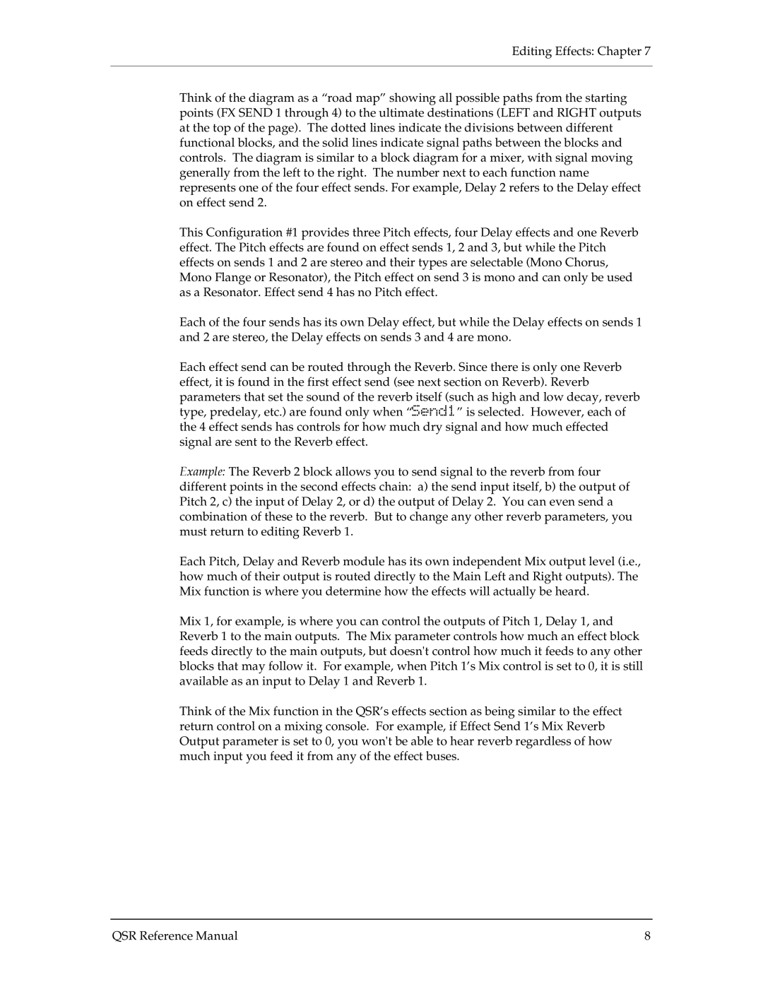
Think of the diagram as a “road map” showing all possible paths from the starting points (FX SEND 1 through 4) to the ultimate destinations (LEFT and RIGHT outputs at the top of the page). The dotted lines indicate the divisions between different functional blocks, and the solid lines indicate signal paths between the blocks and controls. The diagram is similar to a block diagram for a mixer, with signal moving generally from the left to the right. The number next to each function name represents one of the four effect sends. For example, Delay 2 refers to the Delay effect on effect send 2.
This Configuration #1 provides three Pitch effects, four Delay effects and one Reverb effect. The Pitch effects are found on effect sends 1, 2 and 3, but while the Pitch effects on sends 1 and 2 are stereo and their types are selectable (Mono Chorus, Mono Flange or Resonator), the Pitch effect on send 3 is mono and can only be used as a Resonator. Effect send 4 has no Pitch effect.
Each of the four sends has its own Delay effect, but while the Delay effects on sends 1 and 2 are stereo, the Delay effects on sends 3 and 4 are mono.
Each effect send can be routed through the Reverb. Since there is only one Reverb effect, it is found in the first effect send (see next section on Reverb). Reverb parameters that set the sound of the reverb itself (such as high and low decay, reverb type, predelay, etc.) are found only when “Send1” is selected. However, each of the 4 effect sends has controls for how much dry signal and how much effected signal are sent to the Reverb effect.
Example: The Reverb 2 block allows you to send signal to the reverb from four
different points in the second effects chain: a) the send input itself, b) the output of Pitch 2, c) the input of Delay 2, or d) the output of Delay 2. You can even send a combination of these to the reverb. But to change any other reverb parameters, you must return to editing Reverb 1.
Each Pitch, Delay and Reverb module has its own independent Mix output level (i.e., how much of their output is routed directly to the Main Left and Right outputs). The Mix function is where you determine how the effects will actually be heard.
Mix 1, for example, is where you can control the outputs of Pitch 1, Delay 1, and Reverb 1 to the main outputs. The Mix parameter controls how much an effect block feeds directly to the main outputs, but doesn't control how much it feeds to any other blocks that may follow it. For example, when Pitch 1’s Mix control is set to 0, it is still available as an input to Delay 1 and Reverb 1.
Think of the Mix function in the QSR’s effects section as being similar to the effect return control on a mixing console. For example, if Effect Send 1’s Mix Reverb Output parameter is set to 0, you won't be able to hear reverb regardless of how much input you feed it from any of the effect buses.
QSR Reference Manual | 8 |