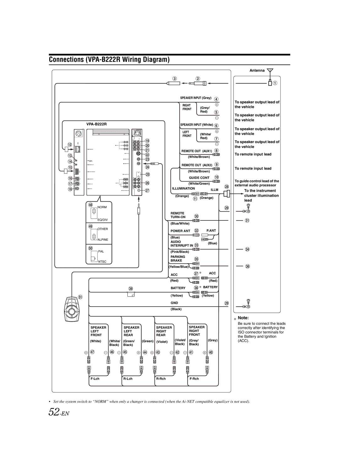
Connections (VPA-B222R Wiring Diagram)
| SPEAKER INPUT (Grey) | |
| RIGHT | (Grey/ |
| FRONT | |
| Red) | |
|
| |
SPEAKER INPUT (White) | ||
| LEFT | (White/ |
| FRONT | |
| Red) | |
|
| |
| REMOTE OUT (AUX1) | |
| (White/Brown) | |
| REMOTE OUT (AUX2) | |
| (White/Brown) | |
| GUIDE CONT | |
| (White/Green) | |
| ILLUMINATION | ILLM |
|
| |
| (Orange) | (Orange) |
|
| |
| REMOTE |
|
|
| |
| (Blue/White) |
|
| POWER ANT | P.ANT |
| (Blue) |
|
| AUDIO | (Blue) |
| INTERRUPT IN | |
|
| |
| (Pink/Black) |
|
| PARKING |
|
| BRAKE |
|
| (Yellow/Blue) |
|
| ACC | ACC |
|
| |
| (Red) | (Red) |
| BATTERY | BATTERY |
|
| |
| (Yellow) | (Yellow) |
| GND |
|
| (Black) |
|
SPEAKER |
| SPEAKER | SPEAKER |
| SPEAKER |
|
LEFT |
| LEFT | RIGHT |
| RIGHT |
|
FRONT |
| REAR | REAR |
| FRONT |
|
(White) | (White/ | (Green/ | (Green) (Violet) | (Violet/ | (Grey/ | (Grey) |
| Black) | Black) |
| Black) | Black) |
|
Antenna
To speaker output lead of the vehicle
To speaker output lead of the vehicle
To speaker output lead of the vehicle
To speaker output lead of the vehicle
To remote input lead
To remote input lead
To guide control lead of the external audio processor
To the instrument cluster illumination lead
![]() Note:
Note:
Be sure to connect the leads correctly after identifying the ISO connector terminals for the Battery and lgnition (ACC).
•Set the system switch to “NORM” when only a changer is connected (when the