Contents
CoreModule PC/104 Single Board Computer Reference Manual
Audience Assumptions
Contents
Appendix a
Table A-1
Reference Manual CoreModule
Purpose of this Manual
Specifications
Chip Specifications
About This Manual
Other Ampro Products
Related Ampro Products
CoreModule 420 Support Products
Other CoreModule Products
Chapter
Reference Manual CoreModule
PC/104 Architecture
Product Overview
Module Features
Product Description
CPU
Chapter
CRT
Bios
Block Diagram
Atlas
Major Integrated Circuits ICs
Chip Type Mfg Model Description Function
Stpc
IDE
Connectors, Jumpers, and LEDs
Connector Definitions
Jack/Plug # Access Description
LED Definitions
Jumper # Installed Removed
Indicator Definition
Jumper Definitions
JP6 JP9 JP7 JP8 JP5 JP4 JP1
Dimension
Specifications
Physical Specifications
Mechanical Specifications
Power Specifications
Environmental Specifications
Thermal/Cooling Requirements
Reference Manual
Overview
Hardware
Memory
CPU U14
Use Address Size Memory hole size selected
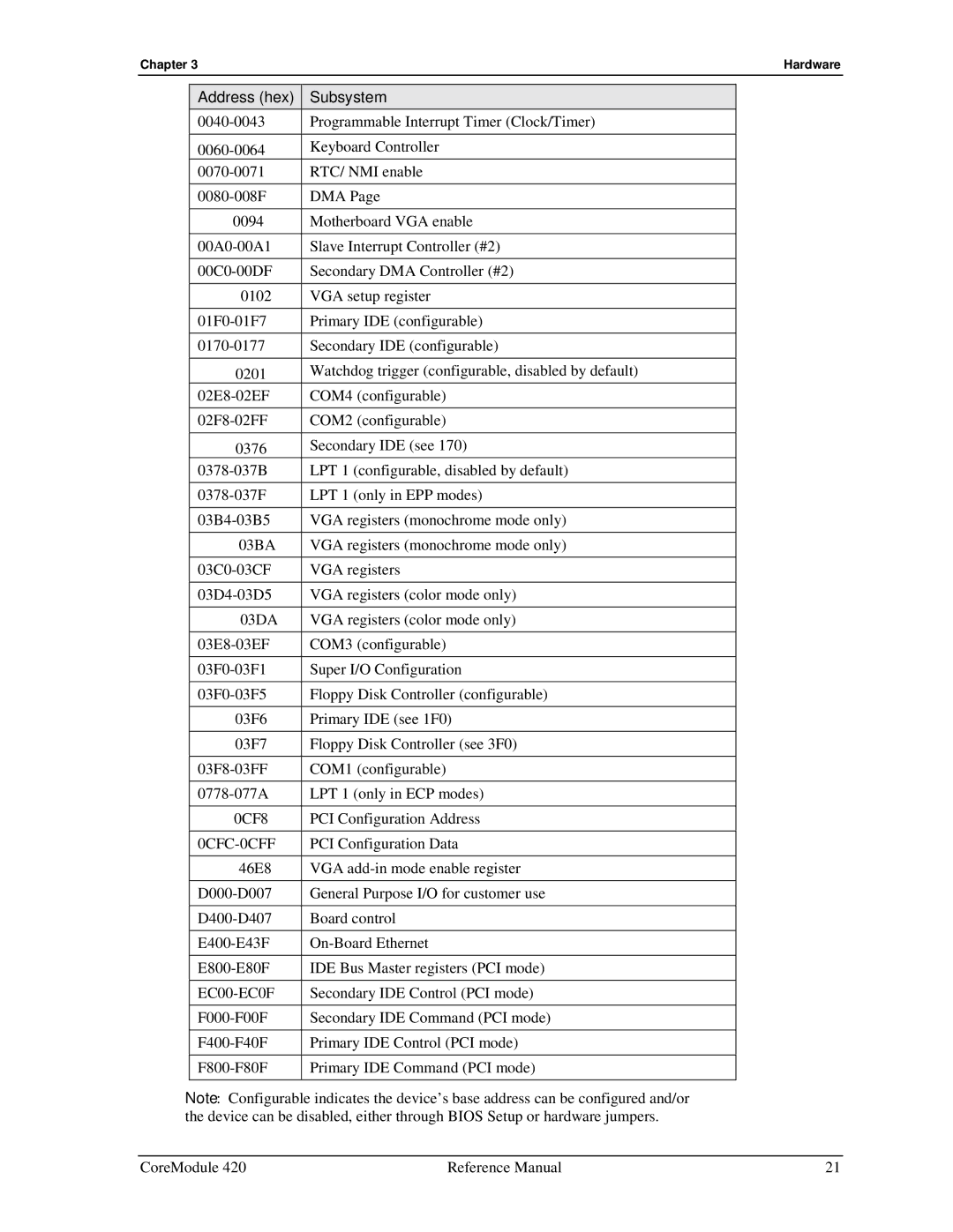
Address Map
Interrupt Channel Assignments
EC00-EC0F
0CFC-0CFF
PC/104 Bus Interface P1A,B,C,D
Pin # Signal Description P1 Row a
Pin # Signal Description P1 Row B
Pin # Signal Description P1 Row C
Pin # Signal Description P1 Row D
DRQ5
DRQ6
DRQ7
Pdrq
Pin # Signal Description
Reset
IDE Interface J6
IDEPCS1
Pior
Pdack
Pirq
CompactFlash Socket J12
ACT
RDY
Iordy
REG
Floppy/Parallel Port J4
Floppy Disk Drive Port
Parallel Port
Rdata
Slin
Step
PD3
Serial 1 to RS485 Conversion
Serial Ports J3, J9, J13, J14
Pin # Signal DB9 # Description
Usbpp
USB Port J10
Usbpwr
Usbpn
Utility Interface J5
Ethernet Interface J2
TX+
RX+
Video LCD/CRT Interface J11
FP2
Tftdclk
Tftde
Tftlp
User Gpio Signals
Miscellaneous
Real Time Clock RTC
Serial Console
Oops! Jumper Bios Recovery
Serial Console Bios Setup
Watchdog Timer
Power Interface J7
Pin Signal Descriptions
Pin # Signal
Reference Manual CoreModule
Bios Setup
Accessing Bios Setup VGA Display
Introduction
Bios Setup Menu Item/Topic
Accessing Bios Setup Serial Console
Bios Setup Opening Screen
Main Bios Setup Menu
Cdrom
Bios Configuration Screen
Chapter Bios Setup
Chapter Bios Setup
Chapter Bios Setup
USB IRQ none, 1, 3, 4, 5, 6, 7, 9, 10, 11, 12, 14, or
Splash Screen Customization
Splash Screen Image Requirements
Converting the Splash Screen File
\splashconvert convert.idf
On-Board Flash Access and Use
Flash Programming Requirements
Building the Example
Installing the Example Application
Flash Boot API
Example Assumptions
Method Contact Information
Appendix a Technical Support
Appendix a
2PH2R44SGA
Appendix B Connector Part Numbers
Teka
Gpio
Appendix B
Index
See also Oops! jumper Bios Setup
Post
64MB Sdram
Serial terminal ANSI-compatible
Reference Manual CoreModule