Chapter 3 | Hardware |
Floppy/Parallel Port (J4)
Floppy Disk Drive Port
The Super I/O chip provides the Floppy Disk Controller and the Parallel Port interface (J4). The Floppy Drive interface shares the same connector as the Parallel Port and the signals are multiplexed out of the connector. However, you can only use one of these devices at a time and it must be configured in BIOS Setup Utility. The default device in the BIOS Setup Utility is the Floppy Drive.
The Floppy Disk Controller supports two floppy disk drives from 360kB through 2.88MB and is configured as the floppy interface in the BIOS.
NOTE | Due to the multiplexed nature of the signals for the floppy disk and parallel |
| connector, you can only connect one of these devices at a time. Refer to |
| Chapter 4, BIOS Setup later in this manual when selecting the floppy or |
| parallel device in the BIOS Setup Utility. |
|
|
Parallel Port
The Super I/O chip provides the Parallel Port interface and Floppy Disk Controller, which share the same output connector (J4). The Parallel Port supports the standard parallel,
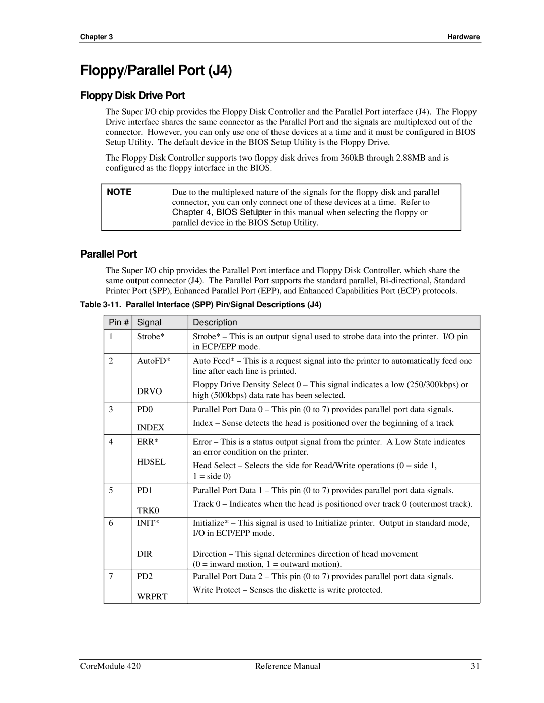
Table
Pin # Signal
Description
1 | Strobe* | Strobe* – This is an output signal used to strobe data into the printer. I/O pin |
|
| in ECP/EPP mode. |
|
|
|
2 | AutoFD* | Auto Feed* – This is a request signal into the printer to automatically feed one |
|
| line after each line is printed. |
| DRVO | Floppy Drive Density Select 0 – This signal indicates a low (250/300kbps) or |
| high (500kbps) data rate has been selected. | |
|
| |
3 | PD0 | Parallel Port Data 0 – This pin (0 to 7) provides parallel port data signals. |
| INDEX | Index – Sense detects the head is positioned over the beginning of a track |
|
| |
|
|
|
4 | ERR* | Error – This is a status output signal from the printer. A Low State indicates |
| HDSEL | an error condition on the printer. |
| Head Select – Selects the side for Read/Write operations (0 = side 1, | |
|
| |
|
| 1 = side 0) |
|
|
|
5 | PD1 | Parallel Port Data 1 – This pin (0 to 7) provides parallel port data signals. |
| TRK0 | Track 0 – Indicates when the head is positioned over track 0 (outermost track). |
|
| |
|
|
|
6 | INIT* | Initialize* – This signal is used to Initialize printer. Output in standard mode, |
|
| I/O in ECP/EPP mode. |
| DIR | Direction – This signal determines direction of head movement |
|
| (0 = inward motion, 1 = outward motion). |
7 | PD2 | Parallel Port Data 2 – This pin (0 to 7) provides parallel port data signals. |
| WRPRT | Write Protect – Senses the diskette is write protected. |
|
| |
|
|
|
CoreModule 420 | Reference Manual | 31 |