Chapter 2 | Product Overview |
Connectors, Jumpers, and LEDs
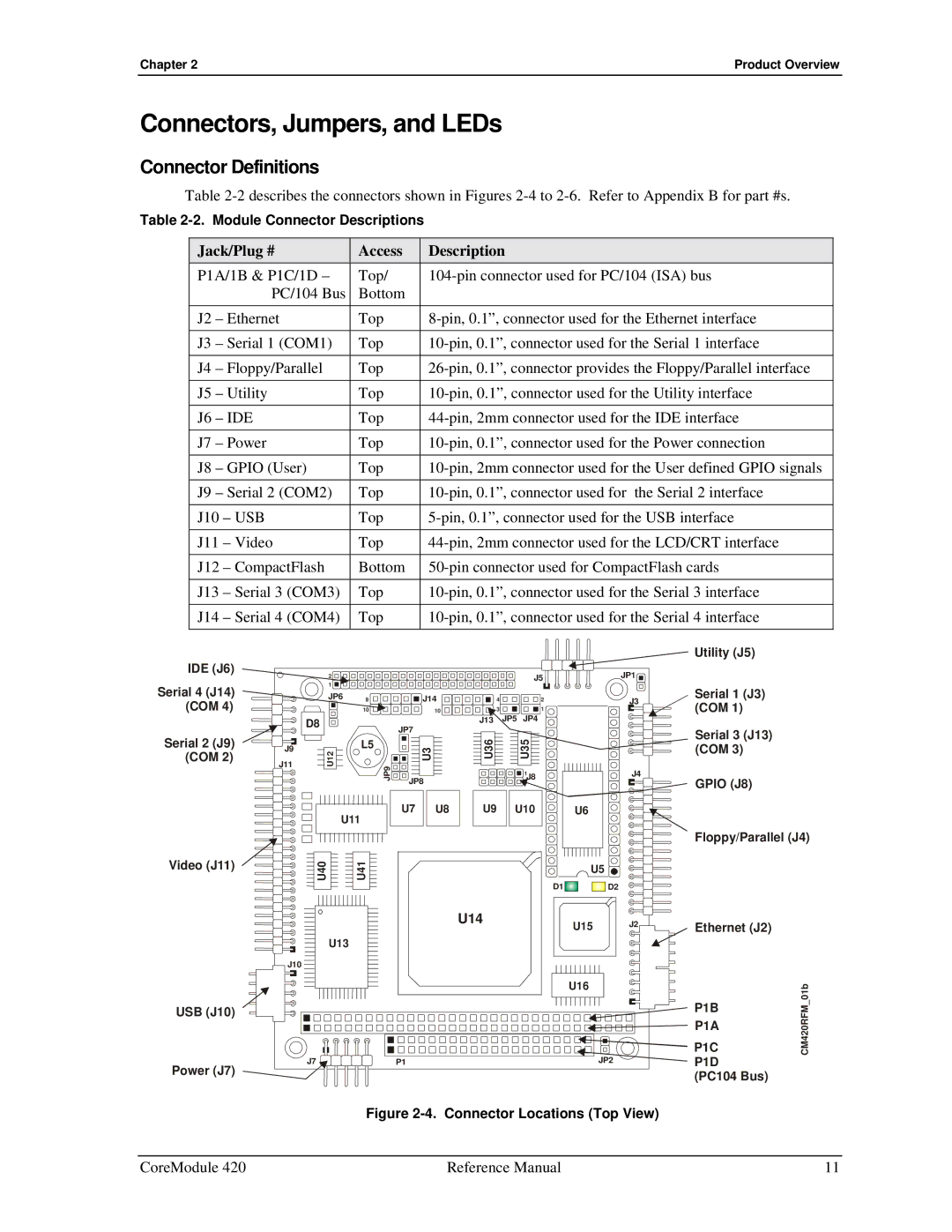
Connector Definitions
Table
Table
Jack/Plug # | Access | Description | ||
P1A/1B & P1C/1D – | Top/ | |||
|
| PC/104 Bus | Bottom |
|
J2 | – Ethernet | Top | ||
|
|
|
| |
J3 | – Serial 1 (COM1) | Top | ||
|
|
|
| |
J4 | – Floppy/Parallel | Top | ||
|
|
|
| |
J5 | – Utility | Top | ||
|
|
|
| |
J6 | – IDE | Top | ||
|
|
|
| |
J7 | – Power | Top | ||
|
|
|
| |
J8 | – GPIO (User) | Top | ||
|
|
|
| |
J9 | – Serial 2 (COM2) | Top | ||
|
|
|
| |
J10 | – USB | Top | ||
|
|
|
| |
J11 | – Video | Top | ||
|
|
|
| |
J12 | – CompactFlash | Bottom | ||
|
|
|
| |
J13 | – Serial 3 (COM3) | Top | ||
|
|
|
| |
J14 | – Serial 4 (COM4) | Top | ||
|
|
|
|
|
IDE (J6)
Serial 4 (J14) (COM 4)
Serial 2 (J9) (COM 2)
J9
J11
2
1
JP6 | 9 | J14 |
| 10 | 10 |
D8JP7
U12 | L5 |
| U3 |
JP9 |
| ||
|
| JP8 | |
| U11 | U7 | U8 |
|
|
| |
| J5 | JP1 |
4 | 2 | J3 |
3 | 1 |
|
J13 JP5 | JP4 |
|
U36 | U35 |
|
| 1 | J4 |
| 2J8 |
|
U9 | U10 | U6 |
Utility (J5)
Serial 1 (J3) (COM 1)
Serial 3 (J13) (COM 3)
GPIO (J8)
Floppy/Parallel (J4)
Video (J11) | U40 | U41 | U5 |
| D2 | ||
|
| D1 |
U14 | U15 | J2 |
|
| |
U13 |
|
|
J10
U16 |
USB (J10)
J7 | P1 | JP2 |
Power (J7) |
|
|
Ethernet (J2)
P1B | _01b | |
CM420RFM | ||
P1C | ||
P1A |
| |
P1D |
| |
(PC104 Bus) |
|
Figure 2-4. Connector Locations (Top View)
CoreModule 420 | Reference Manual | 11 |