Chapter 3 | Hardware |
Serial Console BIOS Setup
The serial console feature may be invoked by entering the appropriate option (port selected) in the Serial Console field of the BIOS and Hardware Settings screen in BIOS Setup. A standard null modem serial cable is used to connect the chosen serial port on the CoreModule 420 (J3 or J9) to a serial terminal or PC. The serial terminal, or PC with communications software, must be set to the following values:
•115k baud
•8 bits
•One stop bit
•No parity
•No hardware handshake
Hot (Serial) Cable
The serial console settings in the BIOS can be overridden by connecting a modified serial cable (or “Hot Cable”) between either serial port (J3 or J9) and the serial terminal, or the PC with communications software, set to the appropriate values outlined above.
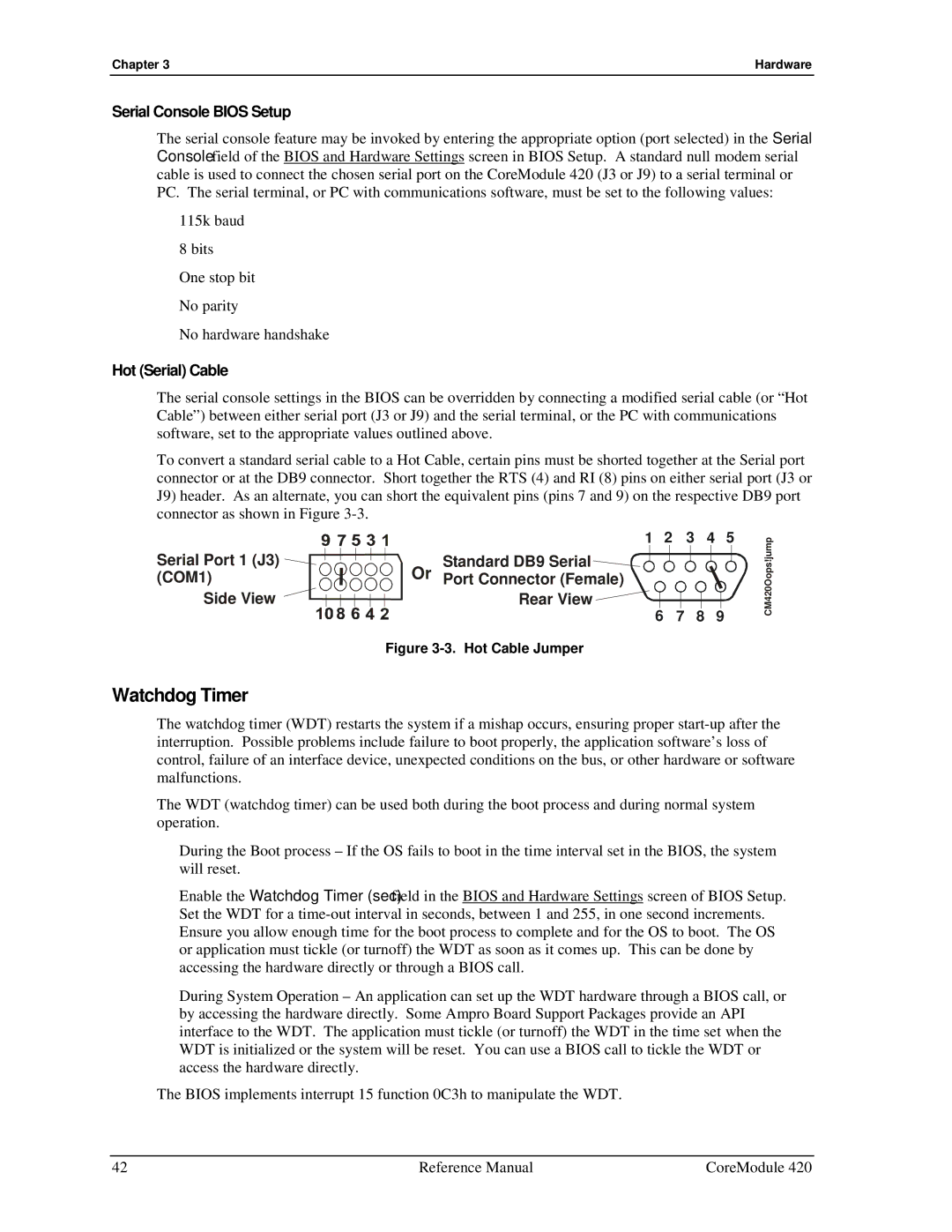
To convert a standard serial cable to a Hot Cable, certain pins must be shorted together at the Serial port connector or at the DB9 connector. Short together the RTS (4) and RI (8) pins on either serial port (J3 or J9) header. As an alternate, you can short the equivalent pins (pins 7 and 9) on the respective DB9 port connector as shown in Figure
1 2 3 4 5
Serial Port 1 (J3) | Or | Standard DB9 Serial |
|
|
|
(COM1) | Port Connector (Female) |
|
|
| |
Side View |
| Rear View | 7 | 8 | 9 |
|
| 6 |
Figure 3-3. Hot Cable Jumper
CM420Oops!jump
Watchdog Timer
The watchdog timer (WDT) restarts the system if a mishap occurs, ensuring proper
The WDT (watchdog timer) can be used both during the boot process and during normal system operation.
•During the Boot process – If the OS fails to boot in the time interval set in the BIOS, the system will reset.
Enable the Watchdog Timer (sec) field in the BIOS and Hardware Settings screen of BIOS Setup. Set the WDT for a
•During System Operation – An application can set up the WDT hardware through a BIOS call, or by accessing the hardware directly. Some Ampro Board Support Packages provide an API interface to the WDT. The application must tickle (or turnoff) the WDT in the time set when the WDT is initialized or the system will be reset. You can use a BIOS call to tickle the WDT or access the hardware directly.
The BIOS implements interrupt 15 function 0C3h to manipulate the WDT.
42 | Reference Manual | CoreModule 420 |