Chapter 3 |
|
| Hardware | |
Table | ||||
|
|
|
|
|
| Pin # | Signal | Description |
|
| 1 | GPIO8 | User defined |
|
|
|
|
|
|
| 2 | GPIO9 | User defined |
|
| 3 | GPIO10 | User defined |
|
|
|
|
|
|
| 4 | GPIO11 | User defined |
|
|
|
|
|
|
| 5 | GPIO12 | User defined |
|
| 6 | GPIO13 | User defined |
|
|
|
|
|
|
| 7 | GPIO14 | User defined |
|
|
|
|
|
|
| 8 | GPIO15 | User defined |
|
| 9 | GND | Ground |
|
| 10 | GND | Ground |
|
|
|
|
|
|
Notes: The shaded area denotes ground.
Oops! Jumper (BIOS Recovery)
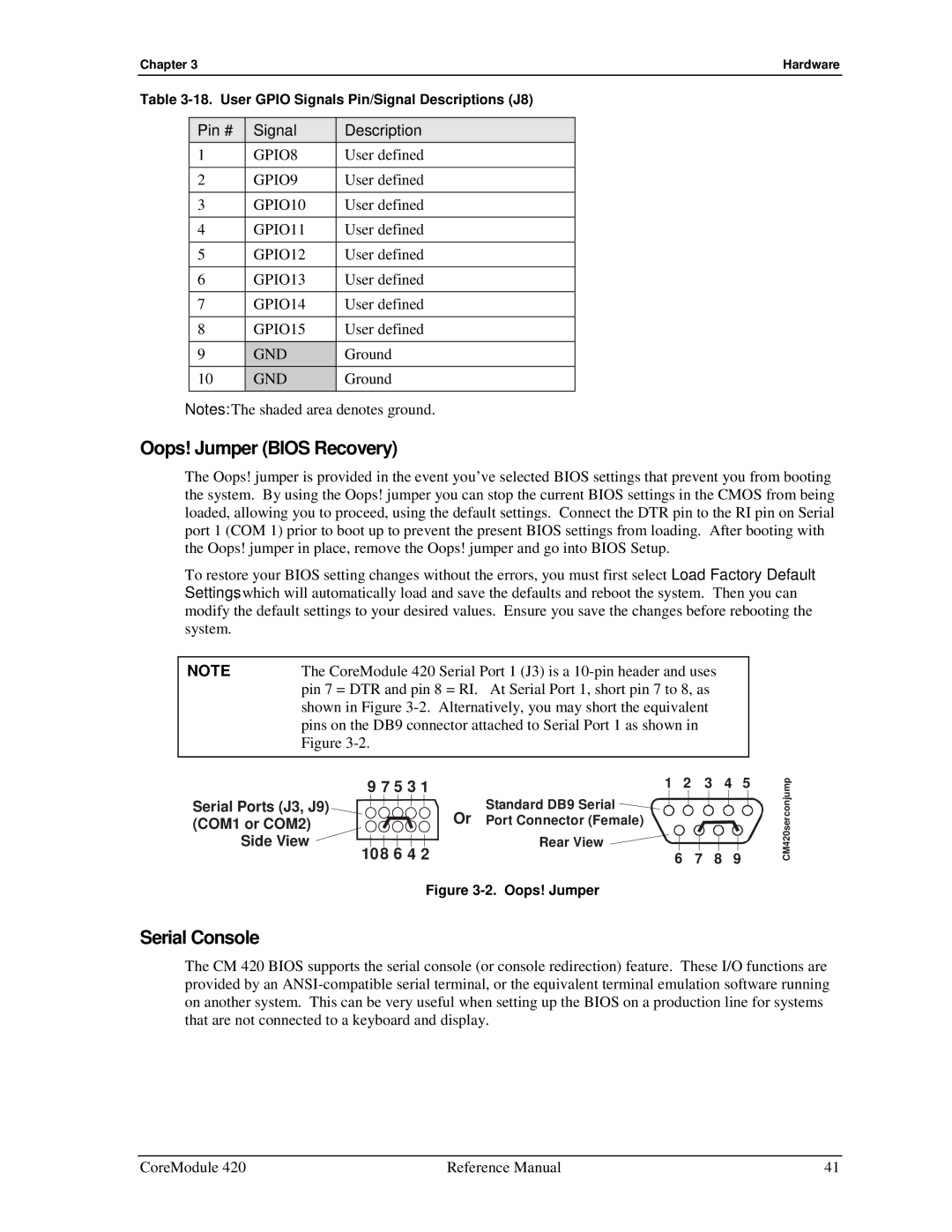
The Oops! jumper is provided in the event you’ve selected BIOS settings that prevent you from booting the system. By using the Oops! jumper you can stop the current BIOS settings in the CMOS from being loaded, allowing you to proceed, using the default settings. Connect the DTR pin to the RI pin on Serial port 1 (COM 1) prior to boot up to prevent the present BIOS settings from loading. After booting with the Oops! jumper in place, remove the Oops! jumper and go into BIOS Setup.
To restore your BIOS setting changes without the errors, you must first select Load Factory Default Settings, which will automatically load and save the defaults and reboot the system. Then you can modify the default settings to your desired values. Ensure you save the changes before rebooting the system.
NOTE | The CoreModule 420 Serial Port 1 (J3) is a |
| pin 7 = DTR and pin 8 = RI. At Serial Port 1, short pin 7 to 8, as |
| shown in Figure |
| pins on the DB9 connector attached to Serial Port 1 as shown in |
| Figure |
|
|
9 7 5 3 1 | 1 | 2 | 3 | 4 | 5 |
Serial Ports (J3, J9) | Standard DB9 Serial |
|
|
|
|
(COM1 or COM2) | Or Port Connector (Female) |
|
|
|
|
Side View | Rear View |
|
|
|
|
108 6 4 2 |
| 6 | 7 | 8 | 9 |
Figure 3-2. Oops! Jumper
CM420serconjump
Serial Console
The CM 420 BIOS supports the serial console (or console redirection) feature. These I/O functions are provided by an
CoreModule 420 | Reference Manual | 41 |