Chapter 3 | Hardware |
•Watchdog Code examples – Ampro has provided source code examples on the CoreModule 420 Doc & SW
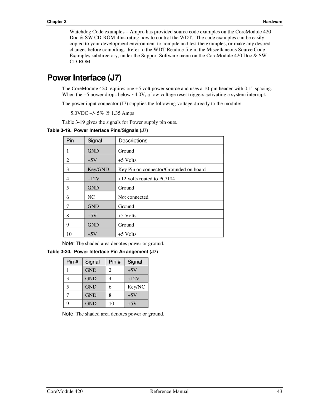
Power Interface (J7)
The CoreModule 420 requires one +5 volt power source and uses a
The power input connector (J7) supplies the following voltage directly to the module:
•5.0VDC +/- 5% @ 1.35 Amps
Table
Table
Pin | Signal | Descriptions |
1 | GND | Ground |
2 | +5V | +5 Volts |
3 | Key/GND | Key Pin on connector/Grounded on board |
4 | +12V | +12 volts routed to PC/104 |
5 | GND | Ground |
6 | NC | Not connected |
7 | GND | Ground |
8 | +5V | +5 Volts |
9 | GND | Ground |
10 | +5V | +5 Volts |
Note: The shaded area denotes power or ground.
Table
Pin # | Signal | Pin # | Signal |
1 | GND | 2 | +5V |
3 | GND | 4 | +12V |
5 | GND | 6 | Key/NC |
7 | GND | 8 | +5V |
9 | GND | 10 | +5V |
|
|
|
|
Note: The shaded area denotes power or ground.
CoreModule 420 | Reference Manual | 43 |