Chapter 2 Product Overview
This introduction presents general information about the PC/104 architecture and the CoreModule 420 single board computer (SBC). After reading this chapter you should understand:
•PC/104 Concept
•CoreModule 420 architecture
•CoreModule 420 features
•Major components
•Connectors
•Specifications
PC/104 Architecture
The PC/104 architecture affords a great deal of flexibility in system design. You can build a simple system using only a CoreModule 420, with input/output devices connected to its serial or parallel ports, and a solid state disk drive or CompactFlash card in the respective bytewide socket, or CompactFlash socket. To expand a simple CoreModule system, simply add
•Additional serial and parallel ports
•Analog or digital I/O
•PCMCIA interfaces
•Sound cards
PC/104 expansion modules can be stacked with the CoreModule 420 avoiding the need for card cages and backplanes. The PC/104 expansion modules can be mounted directly to the PC/104 bus connector of the CoreModule 420.
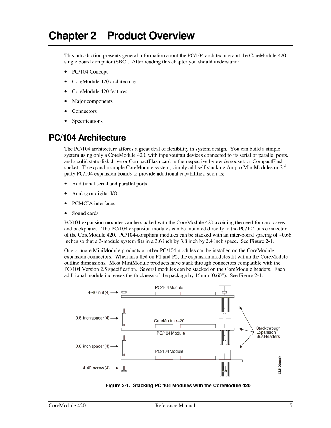
One or more MiniModule products or other PC/104 modules can be installed on the CoreModule expansion connectors. When installed on P1 and P2, the expansion modules fit within the CoreModule outline dimensions. Most MiniModule products have stack through connectors compatible with the PC/104 Version 2.5 specification. Several modules can be stacked on the CoreModule headers. Each additional module increases the thickness of the package by 15mm (0.60”). See Figure
PC/104 Module
![]()
0.6 inch spacer (4) ![]()
0.6inch spacer (4) ![]()
![]()
CoreModule 420
PC/104 Module
PC/104 Module
Stackthrough
Expansion
Bus Headers
CM420stack
Figure 2-1. Stacking PC/104 Modules with the CoreModule 420
CoreModule 420 | Reference Manual | 5 |