LittleBoard Single Board Computer Reference Manual
Audience Assumptions
Contents
Appendix a
List of Tables
Table A-1
Purpose of this Manual
Specifications
Reference Material
LittleBoard 550 Support Products
Related Ampro Products
Other LittleBoard Products
Other Ampro Products
Chapter
EBX Architecture
Product Overview
Stacking PC/104 Modules with the LittleBoard
Product Description
Board Features
Chapter
Chapter
ATA
Block Diagram
CPU
Major Integrated Circuits ICs
Chip Type Mfg Model Description Function
VIA
DIMM1
Connector Definitions
Jack # Signal Description
Additional Components
Northb
Jumper Definitions
Jumper # Installed Removed/Installed
Default
Indicator Definition
Thb
Physical Specifications
Specifications
Dimension
LittleBoard 550 Dimensions Top view, #1
Mechanical Specifications
115 705 415 730 200 050 350 800 600 385 345
Environmental Specifications
Power Specifications
Thermal/Cooling Requirements
Reference Manual LittleBoard
USB
Overview
Flash Memory U17
CPU U1
Memory
Sdram Memory DIMM1
Memory Map
Interrupt Channel Assignments
VGA
Address Map
Base Address Function
Address hex Subsystem
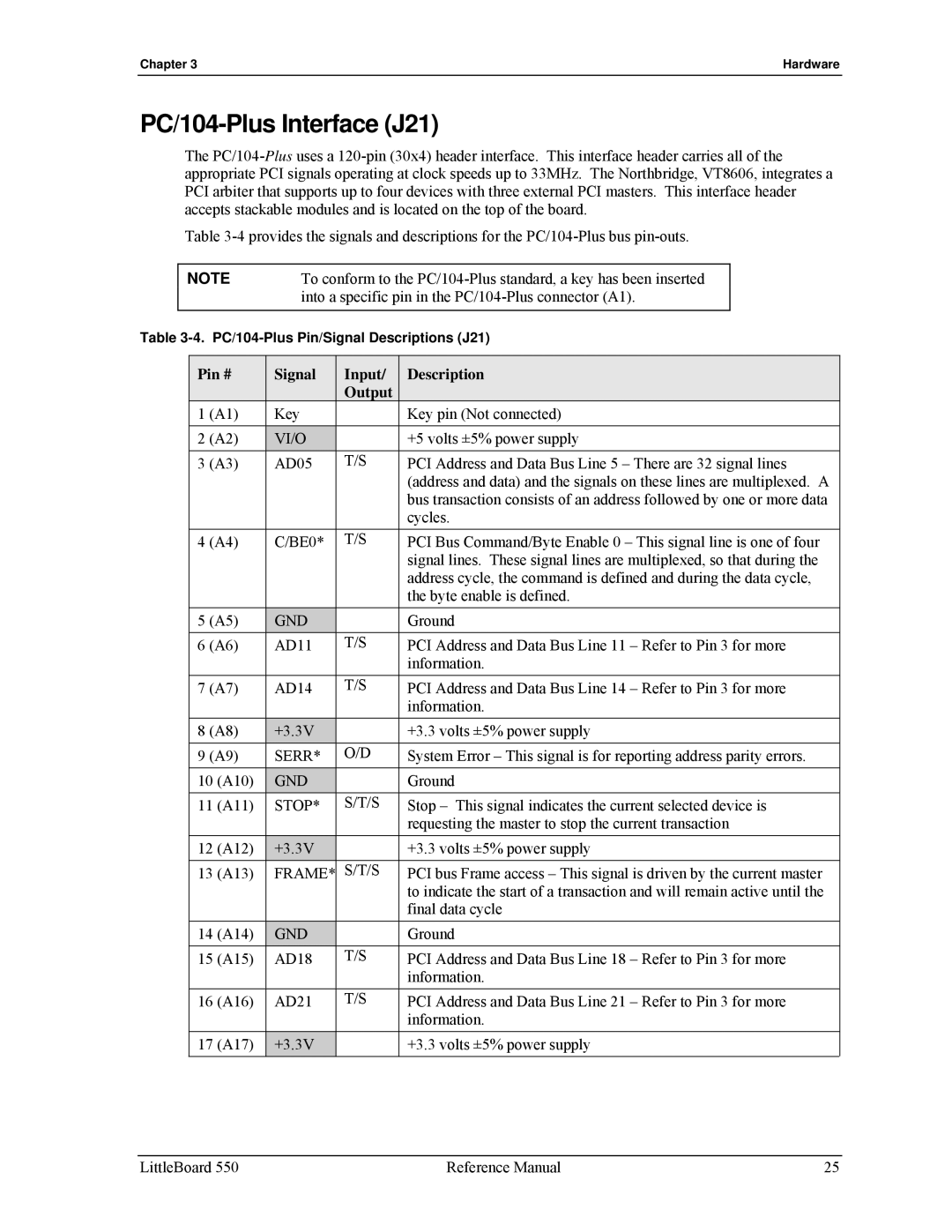
PC/104-Plus Interface J21
Pin # Signal Input Description Output
CLK2
IDSEL0
REQ0
GNT1
Inta
REQ2
CLK0
Intd
CLK3
IDSEL1
REQ1
GNT2
CLK1
IDSEL2
IDSEL3
GNT0
PC/104 Interface J1A,B,C,D
Pin # Signal Description J1 Row a
Pin # Signal Descriptions J1 Row B
DRQ1
DACK3
DRQ3
DACK1
Pin # Signal Descriptions J1 Row D
Pin # Signal Descriptions J1 Row C
DRQ0
IRQ15
IRQ14
DACK0
IDE Interface J12, J17
Pin # Signal Description
Pdiordy
Pdreq
Pdiow
Pdior
SDD5
SDD8
SDD6
SDD9
SDCS1#
SDA1
SDA0
SDA2
PDCE1
CompactFlash Adapter J23
VCC
Pdrst
PDCE2
Floppy Drive Interface J14
Parallel Port Interface J15
Pin # Signal In/Out Description
RS485 Serial Port Implementation
Serial Interfaces J11, J13
RTS1
DCD1
DSR1
RXD1
DSR3
CTS2
DTR2
DCD3
RTS4
DCD4
DSR4
RXD4
Utility 1 Interface J16
Utility Interfaces
Mouse Interface
Utility 2 Interface J24
System Management Bus SMBus
Component Address Binary
USB Signals USB0 and USB1
Sdram Eprom
Mdata
Susc
Pwrbt
Batlow
Utility 3 Interface J18
USB Signals USB2 and USB3
TX+
Ethernet Interfaces J7, J32
Audio Interface J28
CDL
Videol
Videognd
Videor
CRT Interface
Video Interfaces J3, J4, J5, J31
LCD Interface
Enavdd
Lvds Interface
Pin # Signal Description Line Channel
Real Time Clock RTC
Temperature Monitoring
Oops! Jumper Bios Recovery
Miscellaneous
Hot Cable Jumper
Watchdog Timer
TAG
Power Interface J10
Power Monitor
CPU Fan
Reference Manual LittleBoard
Introduction
Accessing Bios Setup VGA Display
Bios Setup Menu Item/Topic
Accessing Bios Setup Serial Console
Bios Setup Opening Screen
Bios Menus
Drive Assignment
Bios Configuration Screen
Drive Configurations and Boot Options
Date & Time
# of Floppy Drives Bios Settings
Drive and Boot Options
Boot Order
User Interface Options
Keyboard and Mouse Configuration
User Interface
Memory
Memory Control Options
Power Management
Power Management and Advanced User Options
Advanced features
On-Board Serial Ports
On-Board LPT Port
On-Board Controllers
Video, Flat Panel, and Audio Options
On-Board Video
PCI, Plug n Play, and Interrupt Assignments
Chapter Bios Setup
Chapter Bios Setup
Chapter Bios Setup
Splash Screen Image Requirements
Splash Screen Customization
Converting the Splash Screen File
\splashconvert convert.idf
Method Contact Information
Appendix a Technical Support
Appendix a Technical Support
Connector Designation Pin # Mfg Part Number
Appendix B
Appendix C LAN Boot Option
Accessing PXE Boot Agent Bios Setup
PXE Boot Agent Bios Setup
PXE Configuration
PXE Boot Agent Setup Screen
TCP/IP Configuration
RPL Configuration
NetWare Configuration
CRT
CD-ROM
Post
Documentation and Support Software Doc & SW CD-ROM
WDT
Supported features
Reference Manual LittleBoard