Chapter 4 | BIOS Setup |
•If the [CRT+LCD] is selected, the same video information is shown on both displays simultaneously.
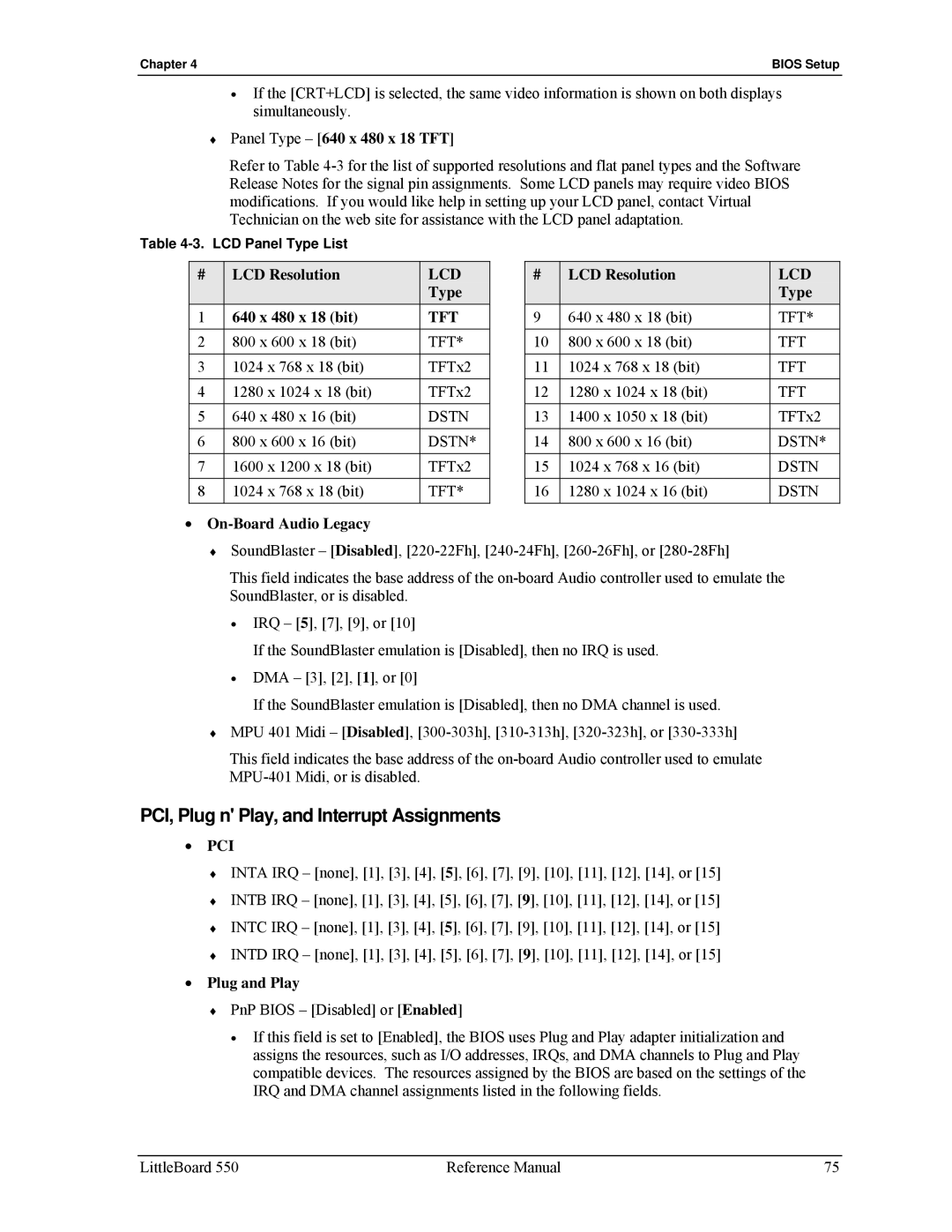
♦Panel Type – [640 x 480 x 18 TFT]
Refer to Table
Table
# | LCD Resolution | LCD |
|
| Type |
1 | 640 x 480 x 18 (bit) | TFT |
|
|
|
2 | 800 x 600 x 18 (bit) | TFT* |
|
|
|
3 | 1024 x 768 x 18 (bit) | TFTx2 |
4 | 1280 x 1024 x 18 (bit) | TFTx2 |
|
|
|
5 | 640 x 480 x 16 (bit) | DSTN |
|
|
|
6 | 800 x 600 x 16 (bit) | DSTN* |
7 | 1600 x 1200 x 18 (bit) | TFTx2 |
|
|
|
8 | 1024 x 768 x 18 (bit) | TFT* |
|
|
|
# | LCD Resolution | LCD |
|
| Type |
9 | 640 x 480 x 18 (bit) | TFT* |
|
|
|
10 | 800 x 600 x 18 (bit) | TFT |
|
|
|
11 | 1024 x 768 x 18 (bit) | TFT |
12 | 1280 x 1024 x 18 (bit) | TFT |
|
|
|
13 | 1400 x 1050 x 18 (bit) | TFTx2 |
|
|
|
14 | 800 x 600 x 16 (bit) | DSTN* |
15 | 1024 x 768 x 16 (bit) | DSTN |
|
|
|
16 | 1280 x 1024 x 16 (bit) | DSTN |
|
|
|
•On-Board Audio Legacy
♦SoundBlaster – [Disabled],
This field indicates the base address of the
•IRQ – [5], [7], [9], or [10]
If the SoundBlaster emulation is [Disabled], then no IRQ is used.
•DMA – [3], [2], [1], or [0]
If the SoundBlaster emulation is [Disabled], then no DMA channel is used.
♦MPU 401 Midi – [Disabled],
This field indicates the base address of the
PCI, Plug n' Play, and Interrupt Assignments
•PCI
♦INTA IRQ – [none], [1], [3], [4], [5], [6], [7], [9], [10], [11], [12], [14], or [15]
♦INTB IRQ – [none], [1], [3], [4], [5], [6], [7], [9], [10], [11], [12], [14], or [15]
♦INTC IRQ – [none], [1], [3], [4], [5], [6], [7], [9], [10], [11], [12], [14], or [15]
♦INTD IRQ – [none], [1], [3], [4], [5], [6], [7], [9], [10], [11], [12], [14], or [15]
•Plug and Play
♦PnP BIOS – [Disabled] or [Enabled]
•If this field is set to [Enabled], the BIOS uses Plug and Play adapter initialization and assigns the resources, such as I/O addresses, IRQs, and DMA channels to Plug and Play compatible devices. The resources assigned by the BIOS are based on the settings of the IRQ and DMA channel assignments listed in the following fields.
LittleBoard 550 | Reference Manual | 75 |