Chapter 3 | Hardware |
CompactFlash Adapter (J23)
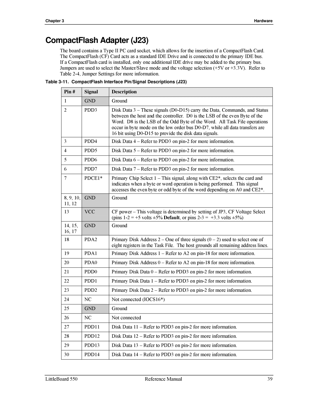
The board contains a Type II PC card socket, which allows for the insertion of a CompactFlash Card. The CompactFlash (CF) Card acts as a standard IDE Drive and is connected to the primary IDE bus. If a CompactFlash card is installed, only one additional IDE drive may be added to the primary bus.
Jumpers are used to select the Master/Slave mode and the voltage selection (+5V or +3.3V). Refer to Table
Table
Pin # | Signal | Description |
|
|
|
1 | GND | Ground |
2 | PDD3 | Disk Data 3 – These signals |
|
| between the host and the controller. D0 is the LSB of the even Byte of the |
|
| Word. D8 is the LSB of the Odd Byte of the Word. All Task File operations |
|
| occur in byte mode on the low order bus |
|
| 16 bit using |
3 | PDD4 | Disk Data 4 – Refer to PDD3 on |
|
|
|
4 | PDD5 | Disk Data 5 – Refer to PDD3 on |
|
|
|
5 | PDD6 | Disk Data 6 – Refer to PDD3 on |
|
|
|
6 | PDD7 | Disk Data 7 – Refer to PDD3 on |
|
|
|
7 | PDCE1* | Primary Chip Select 1 – This signal, along with CE2*, selects the card and |
|
| indicates when a byte or word operation is being performed. This signal |
|
| accesses the even byte or odd byte of the word depending on A0 and CE2*. |
8, 9, 10, | GND | Ground |
11, 12 |
|
|
|
| |
13 | VCC | CF power – This voltage is determined by setting of JP3, CF Voltage Select |
|
| (pins |
14, 15, | GND | Ground |
16, 17 |
|
|
18 | PDA2 | Primary Disk Address 2 – One of three signals (0 – 2) used to select one of |
|
| eight registers in the Task File. The host grounds all remaining address lines. |
19 | PDA1 | Primary Disk Address 1 – Refer to A2 on |
|
|
|
20 | PDA0 | Primary Disk Address 0 – Refer to A2 on |
|
|
|
21 | PDD0 | Primary Disk Data 0 – Refer to PDD3 on |
|
|
|
22 | PDD1 | Primary Disk Data 1 – Refer to PDD3 on |
|
|
|
23 | PDD2 | Primary Disk Data 2 – Refer to PDD3 on |
|
|
|
24 | NC | Not connected (IOCS16*) |
|
|
|
25 | GND | Ground |
26 | NC | Not connected |
|
|
|
27 | PDD11 | Disk Data 11 – Refer to PDD3 on |
|
|
|
28 | PDD12 | Disk Data 12 – Refer to PDD3 on |
|
|
|
29 | PDD13 | Disk Data 13 – Refer to PDD3 on |
|
|
|
30 | PDD14 | Disk Data 14 – Refer to PDD3 on |
|
|
|
LittleBoard 550 | Reference Manual | 39 |