Section |
|
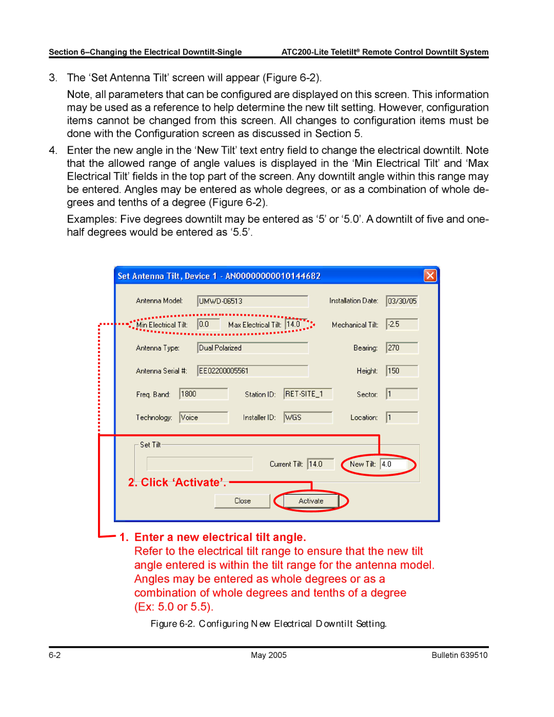
3.The ‘Set Antenna Tilt’ screen will appear (Figure
Note, all parameters that can be configured are displayed on this screen. This information may be used as a reference to help determine the new tilt setting. However, configuration items cannot be changed from this screen. All changes to configuration items must be done with the Configuration screen as discussed in Section 5.
4.Enter the new angle in the ‘New Tilt’ text entry field to change the electrical downtilt. Note that the allowed range of angle values is displayed in the ‘Min Electrical Tilt’ and ‘Max Electrical Tilt’ fields in the top part of the screen. Any downtilt angle within this range may be entered. Angles may be entered as whole degrees, or as a combination of whole de- grees and tenths of a degree (Figure
Examples: Five degrees downtilt may be entered as ‘5’ or ‘5.0’. A downtilt of five and one- half degrees would be entered as ‘5.5’.
2.Click ‘Activate’. 
1.Enter a new electrical tilt angle.
Refer to the electrical tilt range to ensure that the new tilt angle entered is within the tilt range for the antenna model. Angles may be entered as whole degrees or as a combination of whole degrees and tenths of a degree (Ex: 5.0 or 5.5).
Figure 6-2. Configuring New Electrical Downtilt Setting.
6- | May 2005 | Bulletin 639510 |