Remove the cable landing cover and bottom plates
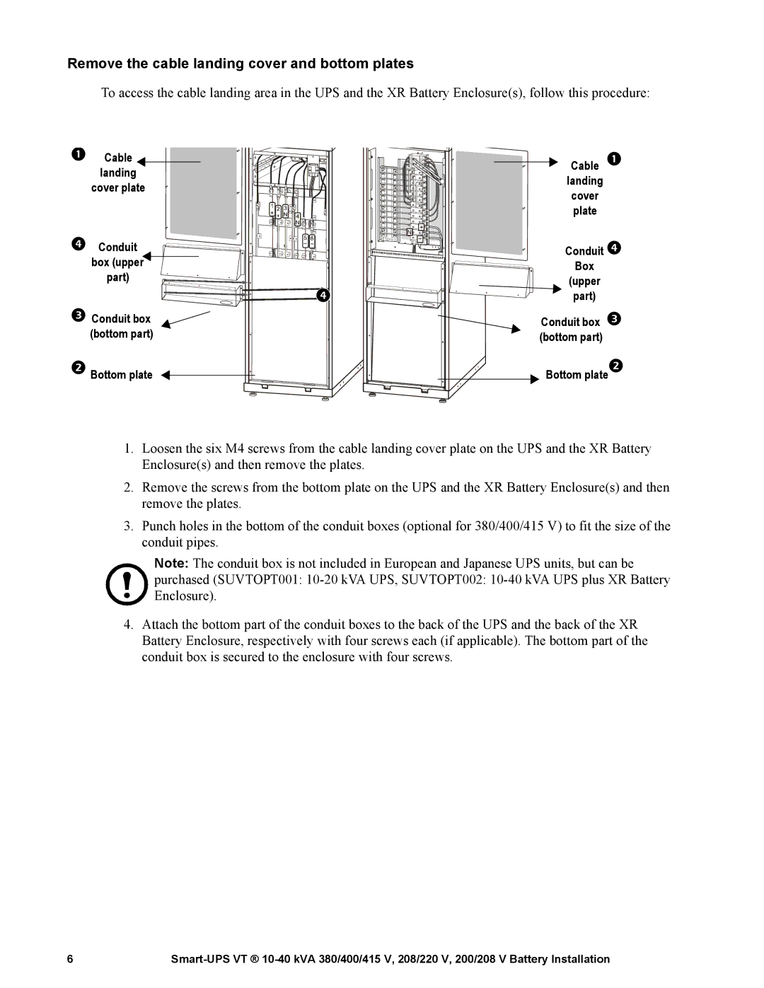
To access the cable landing area in the UPS and the XR Battery Enclosure(s), follow this procedure:
Cable landing
cover plate
![]() +
+![]()
N ![]()
Conduit ![]() box (upper
box (upper![]()
part)
![]()
![]()
![]()
![]()
![]()
![]()
![]()
![]()
![]()
![]()
![]()
![]()
![]()
![]()
![]()
![]()
![]()
![]()
![]()
![]()
![]()
![]()
Conduit box (bottom part)
Bottom plate
Cable landing cover
plate
Conduit
Box
(upper
part)
Conduit box
(bottom part)
Bottom plate
1.Loosen the six M4 screws from the cable landing cover plate on the UPS and the XR Battery Enclosure(s) and then remove the plates.
2.Remove the screws from the bottom plate on the UPS and the XR Battery Enclosure(s) and then remove the plates.
3.Punch holes in the bottom of the conduit boxes (optional for 380/400/415 V) to fit the size of the conduit pipes.
Note: The conduit box is not included in European and Japanese UPS units, but can be
purchased (SUVTOPT001:
4.Attach the bottom part of the conduit boxes to the back of the UPS and the back of the XR Battery Enclosure, respectively with four screws each (if applicable). The bottom part of the conduit box is secured to the enclosure with four screws.
6 |
