Operation – Operation Procedures
Parallel System – turning into external bypass.
In bypass operation the batteries are still charged. If a total power off is required, the batteries must be pulled out to the red disconnect line, see the section How to perform a total power off.
Warning
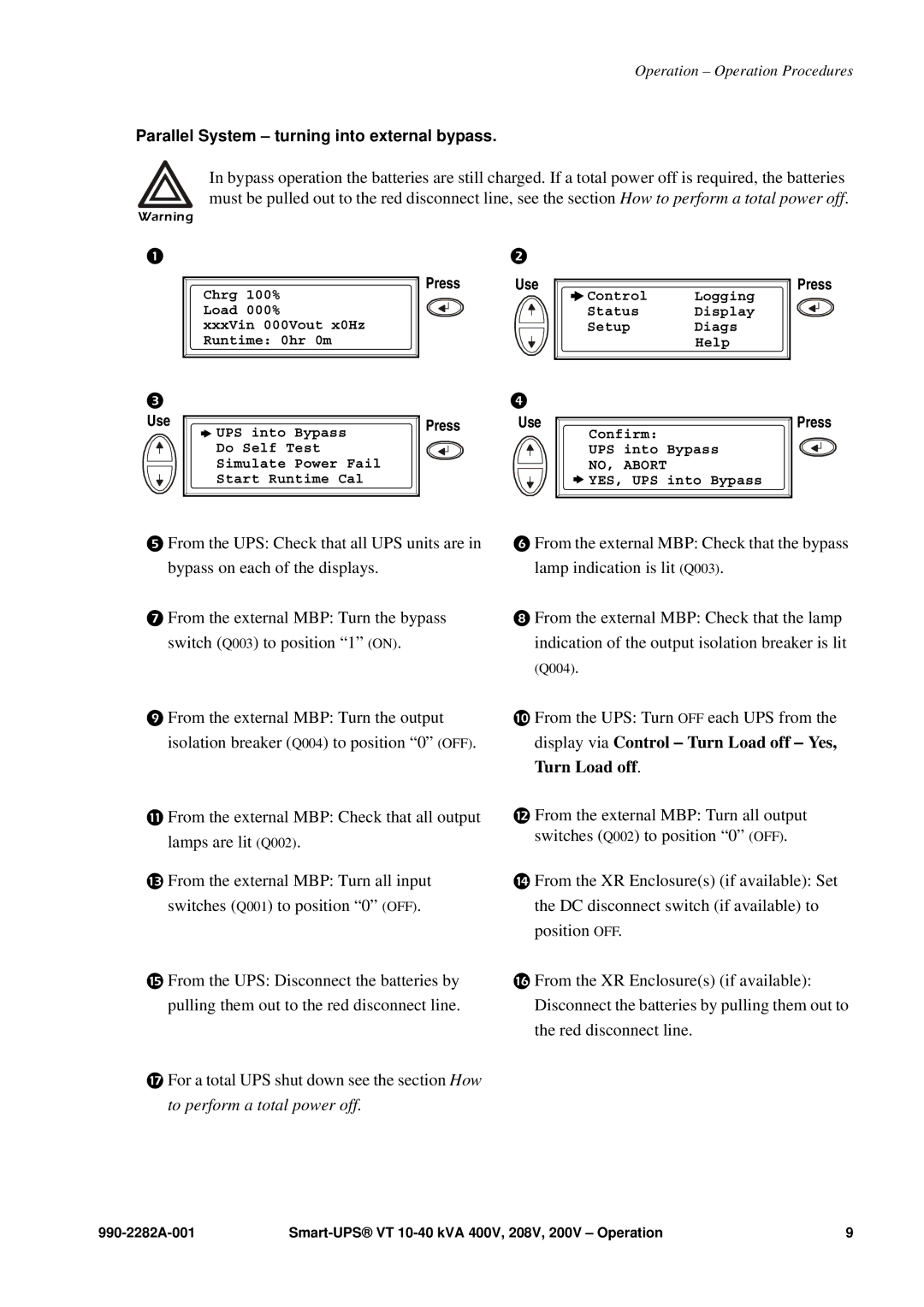
Chrg 100%
Load 000%
xxxVin 000Vout x0Hz Runtime: 0hr 0m
Use
![]() UPS into Bypass Do Self Test Simulate Power Fail Start Runtime Cal
UPS into Bypass Do Self Test Simulate Power Fail Start Runtime Cal
Press | Use | Press |
| Control | Logging |
| Status | Display |
| Setup | Diags |
|
| Help |
Press | Use | Press |
| Confirm: |
|
| UPS into | Bypass |
| NO, ABORT |
|
| YES, UPS | into Bypass |
From the UPS: Check that all UPS units are in bypass on each of the displays.
From the external MBP: Turn the bypass switch (Q003) to position “1” (ON).
From the external MBP: Turn the output isolation breaker (Q004) to position “0” (OFF).
From the external MBP: Check that all output lamps are lit (Q002).
From the external MBP: Turn all input switches (Q001) to position “0” (OFF).
From the UPS: Disconnect the batteries by pulling them out to the red disconnect line.
For a total UPS shut down see the section How to perform a total power off.
From the external MBP: Check that the bypass lamp indication is lit (Q003).
From the external MBP: Check that the lamp
indication of the output isolation breaker is lit (Q004).
From the UPS: Turn OFF each UPS from the display via Control – Turn Load off – Yes, Turn Load off.
From the external MBP: Turn all output switches (Q002) to position “0” (OFF).
From the XR Enclosure(s) (if available): Set the DC disconnect switch (if available) to position OFF.
From the XR Enclosure(s) (if available): Disconnect the batteries by pulling them out to the red disconnect line.
9 |