Manuals
/
Asante Technologies
/
Computer Equipment
/
Switch
Asante Technologies
1000 Repeat steps 1 - 6 for each port you want to assign to a VLAN group
Models:
1000
1
51
88
88
Download
88 pages
37.15 Kb
48
49
50
51
52
53
54
55
<
>
Install
write community string, configuring
Resetting the Device
Setting Community Strings
Performing a Software Upgrade
Accessing the Device
port fiber, SMA connector expandable
3Com SuperStack II Switch
Important For information on using VLAN, see Chap- ter 5,“VLAN.”
Page 51
Image 51
VLAN Groups
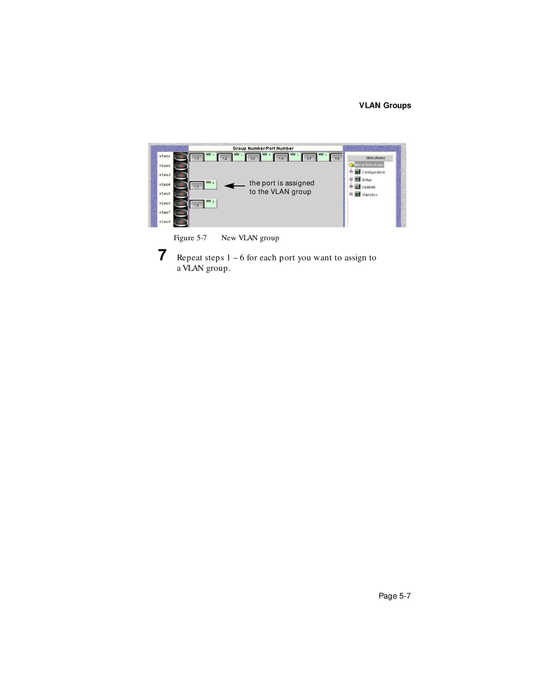
the port is assigned to the VLAN group
Figure
5-7
New VLAN group
7
Repeat steps 1 – 6 for each port you want to assign to a VLAN group.
Page
5-7
Page 50
Page 52
Page 51
Image 51
Page 50
Page 52
Contents
Asanté Technologies, Inc 821 Fox Lane San Jose, CA 1.800.662.9686
3Com SuperStack II Switch
IntraSpection Personality Module
User’s Manual
Copyright Notice
Preface
Table of Contents
Installation
Accessing the Device
VLAN
Management
Technical Support
Menus
Index
Index-i
Page
Chapter Contents
Preface
About This Manual
Audience
Document Conventions
SuperStack II Switch 1000 Personality Module
Introduction
IntraSpection Personality Modules
Management Options
System Requirements
Client
Server
Page
Installing a Personality Module
Installation
8 Click Next to continue
13 Click OK The “IntraSpection Module Installation” window appears
Page
Accessing the Device Page
Accessing the Device
5 Click Apply
Device Information
Device Page Components
Front Panel Image
VLAN Identification Window
Selecting a VLAN Group for Management
Selecting the Device for Management
To deselect the port Click again on the selected port
Selecting a Port for Management
Accessing the Device
To select a port for management
Buttons
Menus
Tables
Table Columns
Page
Management Tasks
Management
Performing Basic Management Functions
Configuration Tasks
Management Task
Important For information on using VLAN, see Chap- ter 5,“VLAN.”
Management
Page
Setting Community Strings
Management
3 Click the Edit Device button
The Map Configuration Table appears, similar to Figure
7 Click Apply The read and write community strings are configured
Click netwAccess
Configuring Network Access Parameters
Click Identify
Configuring Identification Information
Performing a Software Upgrade
Click Validate
Updating the Device Page
Viewing General Device Information
Figure 4-8 Slot Configuration Table
Resetting the Device
Viewing Group Information
Managing Trap Receivers
Adding a Trap Receiver
Click trapReceivers
Modifying a Trap Receiver
Deleting a Trap Receiver
Figure 4-11 Agent Information table
Viewing SNMP Agent Information
Managing the Port Address Table
Viewing the Port Address Table
2 Click Address List
Page
4 Click Apply The entry is deleted
Deleting an Entry
To manually delete an entry in the Port Address Table
Click Modify Open the Address Status drop-down menu and select delete
Table Statistics
Viewing Statistics
Statistics are gathered in the following columns
Figure 4-14 Graph Statistics
Graph Statistics
VLAN Overview
VLAN
Viewing VLAN Groups
VLAN Ports
VLAN Groups
Figure 5-4 VLAN menus
VLAN Menu Items
Creating VLAN Groups
drag the button to the VLAN group drop the button on the VLAN group
Figure 5-5 Selecting a port button
Figure 5-6 Assigning a port to a VLAN group
Port Button Selection
Page
7 Repeat steps 1 - 6 for each port you want to assign to a VLAN group
VLAN Groups
Figure 5-7 New VLAN group
via the VLANView Page
Managing VLAN Groups
Naming a VLAN Group
7 Click Apply
4 Select the VLAN group to be named by clicking once on its row entry
5 Click Modify The Modify Dialog box appears
6 Type a name for the VLAN group in the WGroup- Name field
Disabling a VLAN Group
Viewing Statistics for a VLAN Group
Menus
Page
Menus
VLAN
Address List
Address List
Page
Identify
Device
Agent
Slots
Page
Menus
6-port fiber, SMA connector expandable
Slots
Page
Page
Menus
Upgrade
Network Access
Trap Receivers
Page
Menus
Validate
Validate
Graph
Page
Graph
Page
Menus
Table 6-12 describes each field in the Table menu
Menus
VLAN View
Δ Note For instructions on using this menu, see Chapter 5, “VLAN.”
Table 6-13 describes each field in the VLAN View menu
Page
VLAN View
Page
Technical Support
Contacting Asanté Technical Support
Technical Support Hours
Page
Index
Index-ii
Index-iii
Index-iv
Index-v
write community string, configuring
Windows NT continued
starting server 2-3 World Wide Web browsers supported