ATTO Technology, Inc. | ATTO FibreBridge Installation & Operation Manual | |
|
|
|
|
|
|
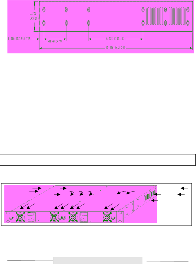
Figure 3.3 Side view with hole dimensions in inches (mm in parentheses)
Environmental
The ATTO FC Rack System is designed to operate in an environment that is
Cooling Airflow
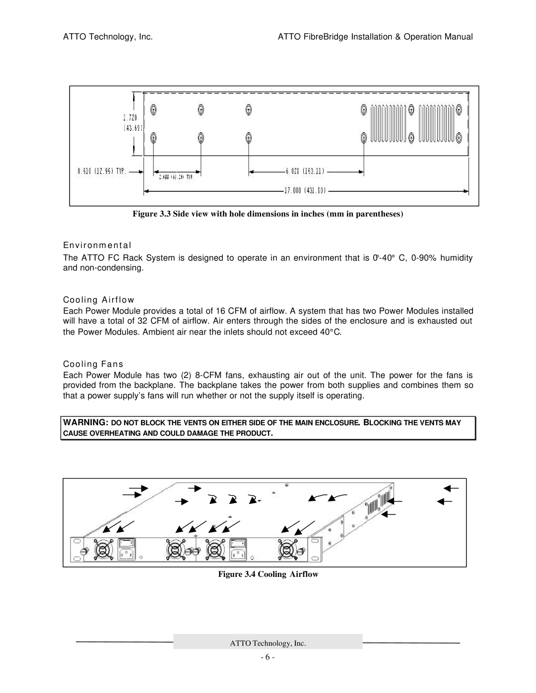
Each Power Module provides a total of 16 CFM of airflow. A system that has two Power Modules installed will have a total of 32 CFM of airflow. Air enters through the sides of the enclosure and is exhausted out the Power Modules. Ambient air near the inlets should not exceed 40°C.
Cooling Fans
Each Power Module has two (2)
WARNING: DO NOT BLOCK THE VENTS ON EITHER SIDE OF THE MAIN ENCLOSURE. BLOCKING THE VENTS MAY CAUSE OVERHEATING AND COULD DAMAGE THE PRODUCT.
Figure 3.4 Cooling Airflow
ATTO Technology, Inc.
- 6 -
