ATTO Technology, Inc. | ATTO FibreBridge Installation & Operation Manual |
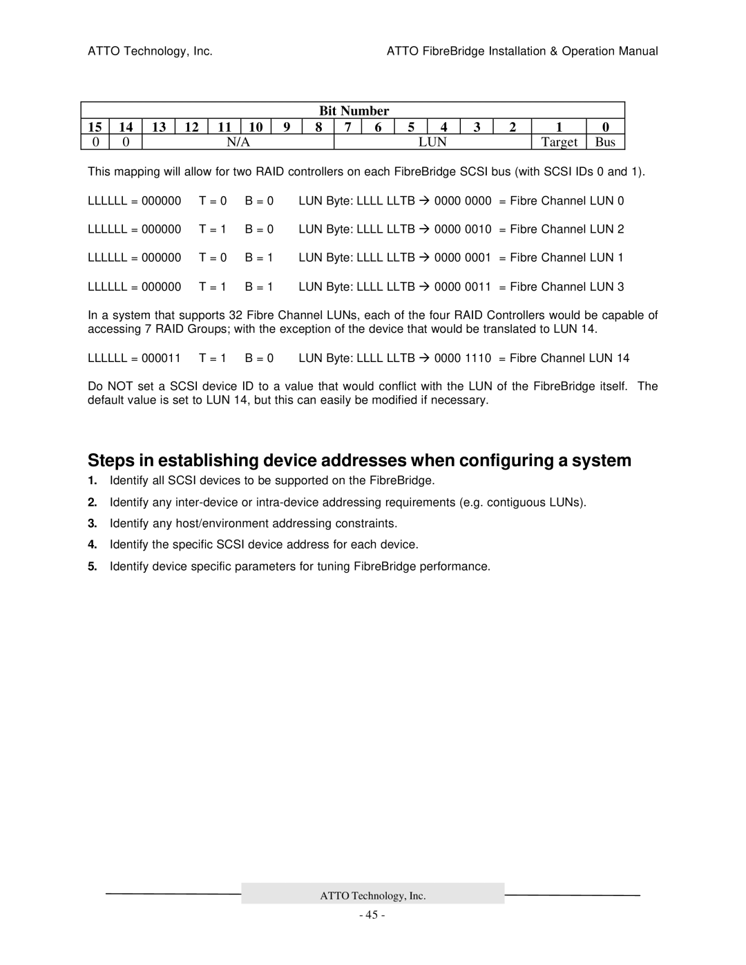
Bit Number
15 | 14 | 13 | 12 | 11 | 10 | 9 | 8 | 7 | 6 | 5 |
| 4 | 3 | 2 | 1 | 0 |
0 | 0 |
|
| N/A |
|
|
|
|
| LUN |
|
| Target | Bus | ||
This mapping will allow for two RAID controllers on each FibreBridge SCSI bus (with SCSI IDs 0 and 1).
LLLLLL = 000000 | T = 0 | B = 0 | LUN Byte: LLLL LLTB à 0000 0000 | = Fibre Channel LUN 0 |
LLLLLL = 000000 | T = 1 | B = 0 | LUN Byte: LLLL LLTB à 0000 0010 | = Fibre Channel LUN 2 |
LLLLLL = 000000 | T = 0 | B = 1 | LUN Byte: LLLL LLTB à 0000 0001 | = Fibre Channel LUN 1 |
LLLLLL = 000000 | T = 1 | B = 1 | LUN Byte: LLLL LLTB à 0000 0011 | = Fibre Channel LUN 3 |
In a system that supports 32 Fibre Channel LUNs, each of the four RAID Controllers would be capable of accessing 7 RAID Groups; with the exception of the device that would be translated to LUN 14.
LLLLLL = 000011 T = 1 B = 0 | LUN Byte: LLLL LLTB à 0000 1110 = Fibre Channel LUN 14 |
Do NOT set a SCSI device ID to a value that would conflict with the LUN of the FibreBridge itself. The default value is set to LUN 14, but this can easily be modified if necessary.
Steps in establishing device addresses when configuring a system
1.Identify all SCSI devices to be supported on the FibreBridge.
2.Identify any
3.Identify any host/environment addressing constraints.
4.Identify the specific SCSI device address for each device.
5.Identify device specific parameters for tuning FibreBridge performance.
ATTO Technology, Inc.
- 45 -