ATTO Technology, Inc. | ATTO FibreBridge Installation & Operation Manual |
Chapter 4: ATTO FibreBridge™ Product Module Integration
This chapter provides an overview of the ATTO FibreBridge Product Modules and their installation process.
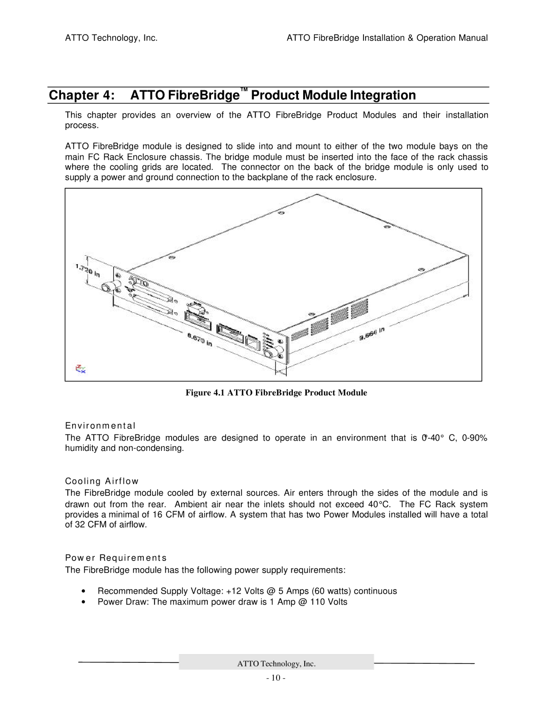
ATTO FibreBridge module is designed to slide into and mount to either of the two module bays on the main FC Rack Enclosure chassis. The bridge module must be inserted into the face of the rack chassis where the cooling grids are located. The connector on the back of the bridge module is only used to supply a power and ground connection to the backplane of the rack enclosure.
Figure 4.1 ATTO FibreBridge Product Module
Environmental
The ATTO FibreBridge modules are designed to operate in an environment that is
Cooling Airflow
The FibreBridge module cooled by external sources. Air enters through the sides of the module and is drawn out from the rear. Ambient air near the inlets should not exceed 40°C. The FC Rack system provides a minimal of 16 CFM of airflow. A system that has two Power Modules installed will have a total of 32 CFM of airflow.
Power Requirements
The FibreBridge module has the following power supply requirements:
∙Recommended Supply Voltage: +12 Volts @ 5 Amps (60 watts) continuous
∙Power Draw: The maximum power draw is 1 Amp @ 110 Volts
ATTO Technology, Inc.
- 10 -