ATTO Technology, Inc. | ATTO FibreBridge Installation & Operation Manual |
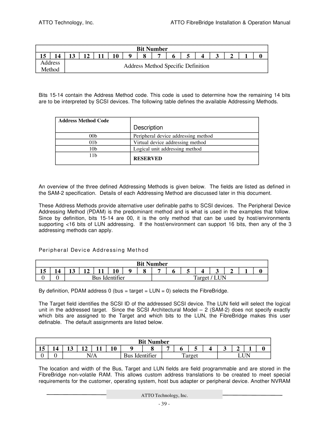
Bit Number
15 | 14 | 13 | 12 | 11 | 10 | 9 | 8 | 7 | 6 | 5 | 4 | 3 | 2 | 1 | 0 |
Address |
|
|
|
| Address Method Specific Definition |
|
|
|
| ||||||
Method |
|
|
|
|
|
|
|
| |||||||
|
|
|
|
|
|
|
|
|
|
|
|
|
| ||
Bits
Address Method Code |
|
| Description |
|
|
00b | Peripheral device addressing method |
01b | Virtual device addressing method |
10b | Logical unit addressing method |
11b | RESERVED |
| |
|
|
An overview of the three defined Addressing Methods is given below. The fields are listed as defined in the
These Address Methods provide alternative user definable paths to SCSI devices. The Peripheral Device Addressing Method (PDAM) is the predominant method and is what is used in the examples that follow. Since by definition, bits
Peripheral Device Addressing Method
Bit Number
15 | 14 | 13 | 12 | 11 | 10 |
| 9 | 8 | 7 | 6 | 5 | 4 | 3 | 2 | 1 | 0 |
0 | 0 |
|
| Bus | Identifier |
|
|
|
|
| Target | / LUN |
|
|
| |
By definition, PDAM address 0 (bus = target = LUN = 0) selects the FibreBridge.
The Target field identifies the SCSI ID of the addressed SCSI device. The LUN field will select the logical unit in the addressed target. Since the SCSI Architectural Model – 2
Bit Number
15 | 14 | 13 | 12 | 11 | 10 | 9 | 8 | 7 | 6 | 5 | 4 | 3 | 2 | 1 | 0 |
0 | 0 |
| N/A |
| Bus Identifier |
| Target |
|
| LUN |
| ||||
The location and width of the Bus, Target and LUN fields are field programmable and are stored in the FibreBridge
ATTO Technology, Inc.
- 39 -