ATTO Technology, Inc. | ATTO FibreBridge Installation & Operation Manual | |
|
|
|
|
|
|
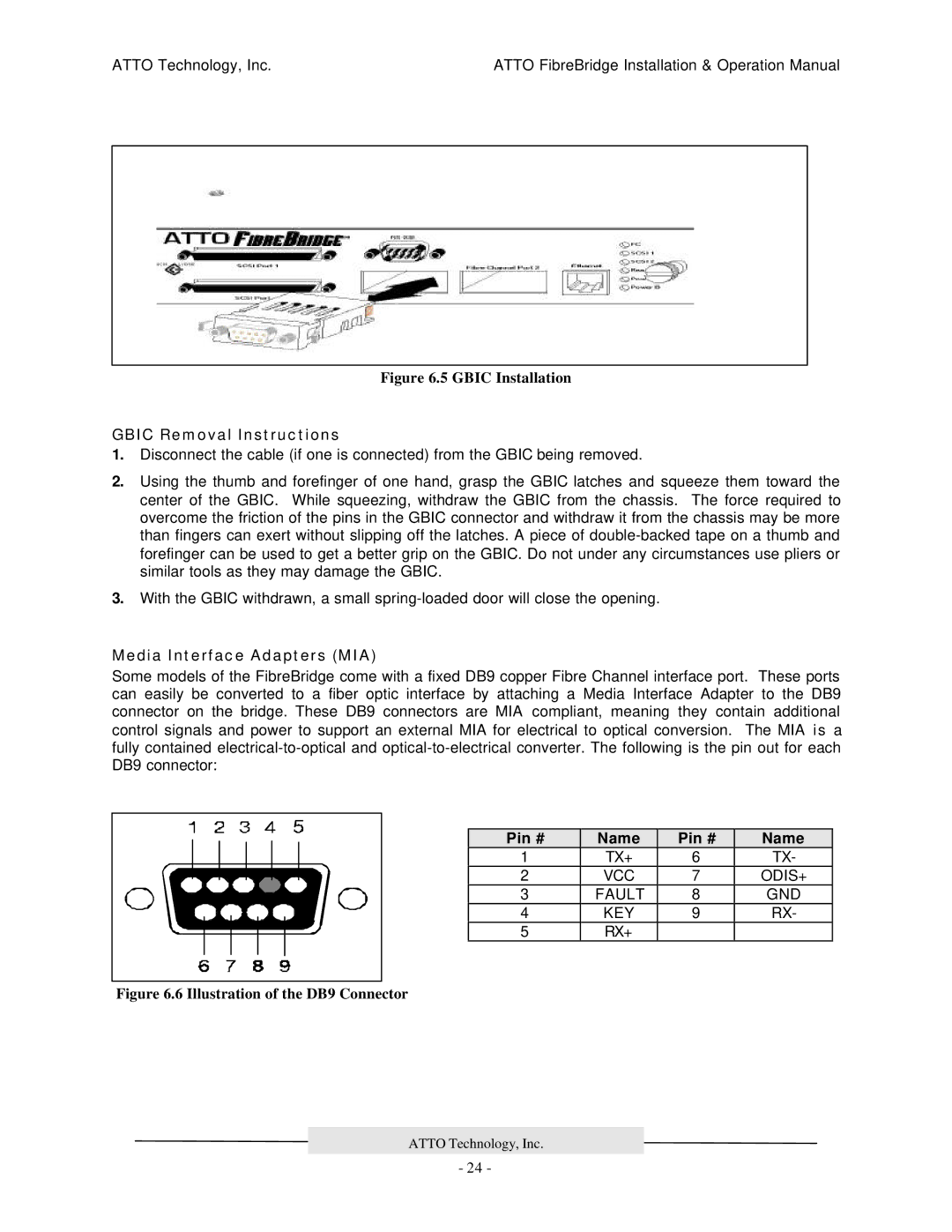
Figure 6.5 GBIC Installation
GBIC Removal Instructions
1.Disconnect the cable (if one is connected) from the GBIC being removed.
2.Using the thumb and forefinger of one hand, grasp the GBIC latches and squeeze them toward the center of the GBIC. While squeezing, withdraw the GBIC from the chassis. The force required to overcome the friction of the pins in the GBIC connector and withdraw it from the chassis may be more than fingers can exert without slipping off the latches. A piece of
3.With the GBIC withdrawn, a small
Media Interface Adapters (MIA)
Some models of the FibreBridge come with a fixed DB9 copper Fibre Channel interface port. These ports can easily be converted to a fiber optic interface by attaching a Media Interface Adapter to the DB9 connector on the bridge. These DB9 connectors are MIA compliant, meaning they contain additional control signals and power to support an external MIA for electrical to optical conversion. The MIA is a fully contained
Pin # | Name | Pin # | Name |
1 | TX+ | 6 | TX- |
2 | VCC | 7 | ODIS+ |
3 | FAULT | 8 | GND |
4 | KEY | 9 | RX- |
5 | RX+ |
|
|
Figure 6.6 Illustration of the DB9 Connector
ATTO Technology, Inc.
- 24 -