ATTO Technology, Inc. | ATTO FibreBridge Installation & Operation Manual |
Fibre Channel Addressing
Fibre Channel World Wide Name (WWN)
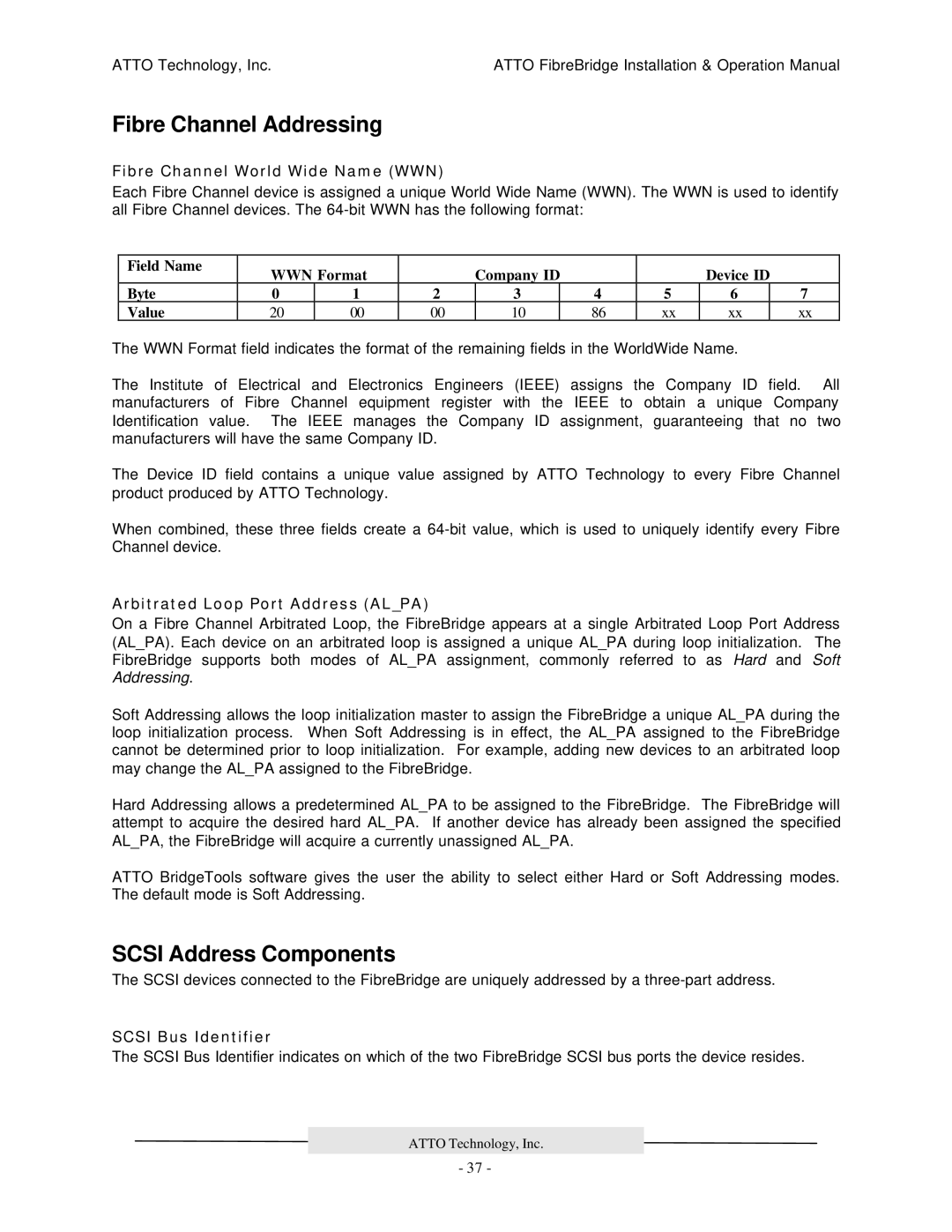
Each Fibre Channel device is assigned a unique World Wide Name (WWN). The WWN is used to identify all Fibre Channel devices. The
Field Name | WWN Format |
| Company ID |
|
| Device ID |
| ||
|
|
|
|
| |||||
Byte | 0 | 1 | 2 | 3 | 4 | 5 | 6 |
| 7 |
Value | 20 | 00 | 00 | 10 | 86 | xx | xx |
| xx |
The WWN Format field indicates the format of the remaining fields in the WorldWide Name.
The Institute of Electrical and Electronics Engineers (IEEE) assigns the Company ID field. All manufacturers of Fibre Channel equipment register with the IEEE to obtain a unique Company Identification value. The IEEE manages the Company ID assignment, guaranteeing that no two manufacturers will have the same Company ID.
The Device ID field contains a unique value assigned by ATTO Technology to every Fibre Channel product produced by ATTO Technology.
When combined, these three fields create a
Arbitrated Loop Port Address (AL_PA)
On a Fibre Channel Arbitrated Loop, the FibreBridge appears at a single Arbitrated Loop Port Address (AL_PA). Each device on an arbitrated loop is assigned a unique AL_PA during loop initialization. The FibreBridge supports both modes of AL_PA assignment, commonly referred to as Hard and Soft Addressing.
Soft Addressing allows the loop initialization master to assign the FibreBridge a unique AL_PA during the loop initialization process. When Soft Addressing is in effect, the AL_PA assigned to the FibreBridge cannot be determined prior to loop initialization. For example, adding new devices to an arbitrated loop may change the AL_PA assigned to the FibreBridge.
Hard Addressing allows a predetermined AL_PA to be assigned to the FibreBridge. The FibreBridge will attempt to acquire the desired hard AL_PA. If another device has already been assigned the specified AL_PA, the FibreBridge will acquire a currently unassigned AL_PA.
ATTO BridgeTools software gives the user the ability to select either Hard or Soft Addressing modes. The default mode is Soft Addressing.
SCSI Address Components
The SCSI devices connected to the FibreBridge are uniquely addressed by a
SCSI Bus Identifier
The SCSI Bus Identifier indicates on which of the two FibreBridge SCSI bus ports the device resides.
ATTO Technology, Inc.
- 37 -