ATTO Technology, Inc. | ATTO FibreBridge Installation & Operation Manual |
∙Power Draw: The maximum power draw is 2 Amps @ 110 Volts for the entire ATTO FC Rack System. When the ATTO FC Rack System has two Power Modules, the entire unit will still draw only 2 Amps @ 110 Volts.
LED Indicator
The green LED indicator on the Power Module will light when the module is correctly installed and the switch is turned on. This LED indicates that power is being drawn from this module and is available on the backplane. A Power Module that is turned on when not installed will not have the LED illuminated. It is not recommended and can be dangerous if the AC power cord is plugged in and the power switch is turned on with an uninstalled Power Module.
IEC Power Receptacle and Switch
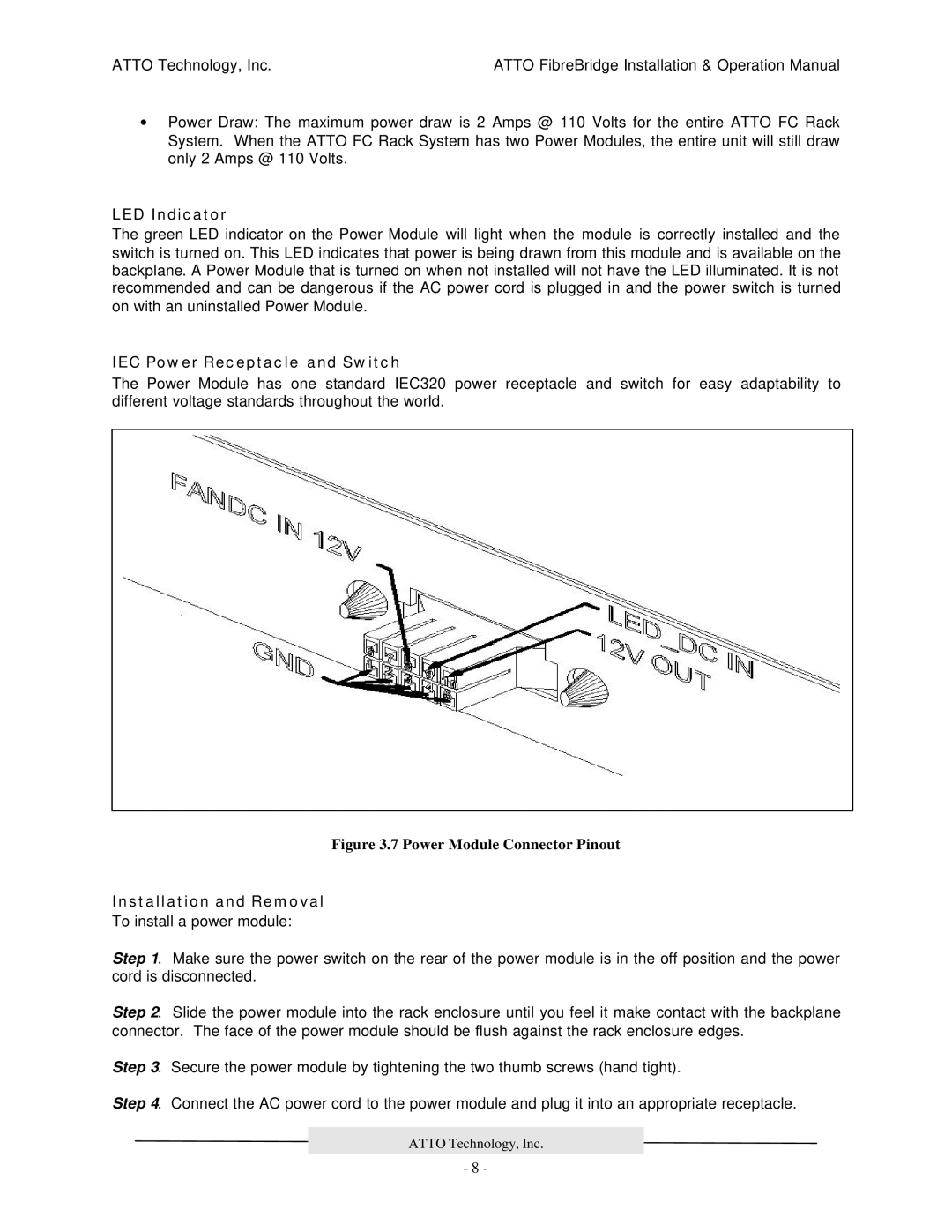
The Power Module has one standard IEC320 power receptacle and switch for easy adaptability to different voltage standards throughout the world.
Figure 3.7 Power Module Connector Pinout
Installation and Removal
To install a power module:
Step 1. Make sure the power switch on the rear of the power module is in the off position and the power cord is disconnected.
Step 2. Slide the power module into the rack enclosure until you feel it make contact with the backplane connector. The face of the power module should be flush against the rack enclosure edges.
Step 3. Secure the power module by tightening the two thumb screws (hand tight).
Step 4. Connect the AC power cord to the power module and plug it into an appropriate receptacle.
ATTO Technology, Inc.
- 8 -