2.2 Rear View
25 | 26 | 28 |
IN |
|
|
|
|
|
| |
OUT |
|
|
|
|
|
| 75 |
CH1 | CH2 | CH3 | CH4 |
|
|
| |
|
| IN |
|
|
|
| ETHERNET |
|
| OUT |
|
MONITOR | AUDIO |
|
|
ALARM I/O | DC12V |
|
29 | 30 | 31 | 32 | 33 | 34 | 35 | 36 37 |
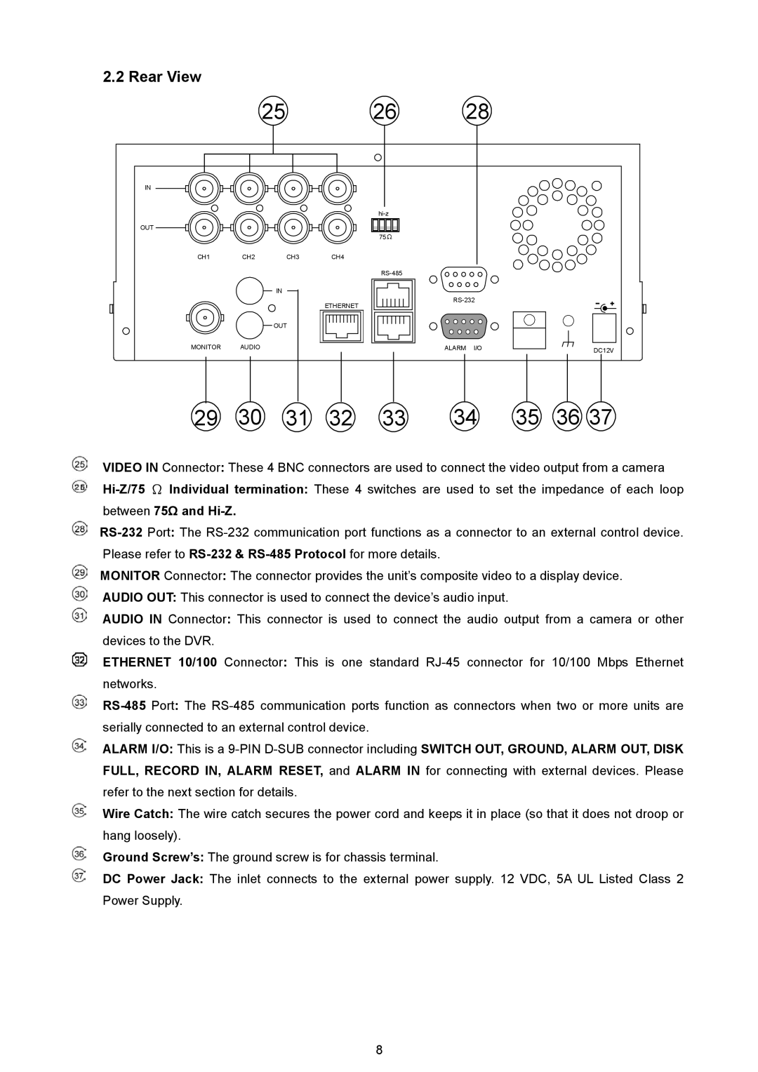
VIDEO IN Connector: These 4 BNC connectors are used to connect the video output from a camera
between 75Ω and Hi-Z.
MONITOR Connector: The connector provides the unit’s composite video to a display device.
AUDIO OUT: This connector is used to connect the device’s audio input.
AUDIO IN Connector: This connector is used to connect the audio output from a camera or other devices to the DVR.
ETHERNET 10/100 Connector: This is one standard
ALARM I/O: This is a
Wire Catch: The wire catch secures the power cord and keeps it in place (so that it does not droop or hang loosely).
Ground Screw’s: The ground screw is for chassis terminal.
DC Power Jack: The inlet connects to the external power supply. 12 VDC, 5A UL Listed Class 2 Power Supply.
8