DCN Wireless Installation and User Instructions Contribution Devices
en 102
19.6.3 Audio inputs
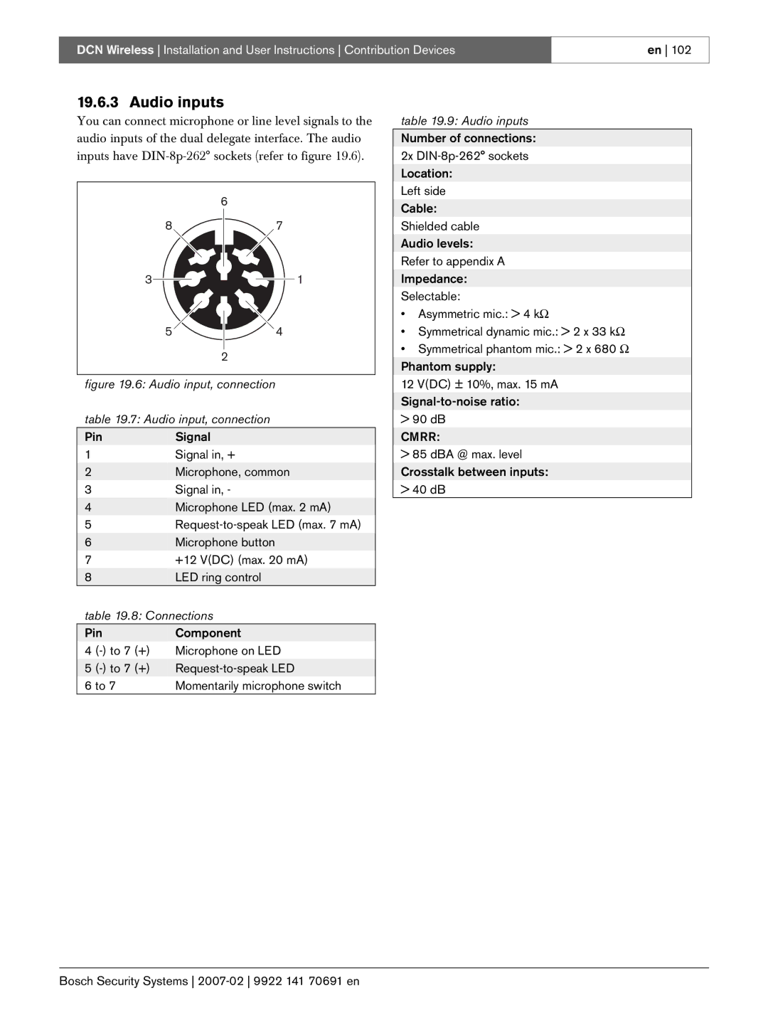
You can connect microphone or line level signals to the audio inputs of the dual delegate interface. The audio inputs have
table 19.9: Audio inputs
Number of connections:
2x
8
3
5 |
6
7
1
4 |
2
Left side
Cable:
Shielded cable
Audio levels:
Refer to appendix A
Impedance:
Selectable:
• Asymmetric mic.: > 4 kΩ | |
• | Symmetrical dynamic mic.: > 2 x 33 kΩ |
• | Symmetrical phantom mic.: > 2 x 680 Ω |
Phantom supply: | |
figure 19.6: Audio input, connection
table 19.7: Audio input, connection
Pin | Signal |
1 | Signal in, + |
2 | Microphone, common |
3 | Signal in, - |
4 | Microphone LED (max. 2 mA) |
5 | |
6 | Microphone button |
7 | +12 V(DC) (max. 20 mA) |
8 | LED ring control |
table 19.8: Connections | |
Pin | Component |
4 | Microphone on LED |
5 | |
6 to 7 | Momentarily microphone switch |
12 V(DC) ± 10%, max. 15 mA |
> 90 dB |
CMRR: |
> 85 dBA @ max. level |
Crosstalk between inputs: |
> 40 dB |